Method and Apparatus for Scalably Encoding/Decoding Video Signal

a video signal and scalable technology, applied in signal generators with optical-mechanical scanning, color television with bandwidth reduction, etc., can solve the problems of inevitably placing a great burden on content providers, mobile devices with varying inherent capabilities of processing or presenting video signals, and difficulty in assigning a wide bandwidth

Inactive Publication Date: 2009-07-02
LG ELECTRONICS INC
View PDF14 Cites 41 Cited by
  • Summary
  • Abstract
  • Description
  • Claims
  • Application Information

AI Technical Summary

Benefits of technology

[0019]According to still another embodiment of the present invention, the sub-frame of the second layer has a screen size smaller than or equal to that of the frame of the first layer.

Problems solved by technology

It is difficult to assign a wide bandwidth, such as the bandwidth required for television (TV) signals, to digital video signals that are transmitted in a wireless manner through mobile phones or notebook computers, which are currently widely used, or through mobile TVs or hand-held Personal Computers (PCs), which will be widely used in the future.
Moreover, such mobile devices inevitably have varying inherent capabilities of processing or presenting video signals.
Therefore, a compressed image must be variously prepared in advance to correspond to such capabilities, which means that video data having various image qualities, with respect to various combined parameters, such as the number of frames per second, the resolution, and the number of bits per pixel, must be provided for a single image source, thus inevitably placing a great burden on content providers.
However, such a scheme must be accompanied by a transcoding (decoding+encoding) procedure, so that a slight time delay occurs at the time of providing the image requested by the mobile device.
Further, the transcoding procedure also requires complicated hardware devices and algorithms depending on the variety of encoding targets.
However, if the bit rate is decreased, the deterioration of image quality becomes serious.
However, since the base layer and the enhanced layer are obtained by encoding the same image content, redundant information (redundancy) exists in video signals of the two layers.

Method used


Image

  • Method and Apparatus for Scalably Encoding/Decoding Video Signal
  • Method and Apparatus for Scalably Encoding/Decoding Video Signal
  • Method and Apparatus for Scalably Encoding/Decoding Video Signal

Examples


Embodiment Construction

[0035]Hereinafter, embodiments of the present invention will be described in detail with reference to the attached drawings.

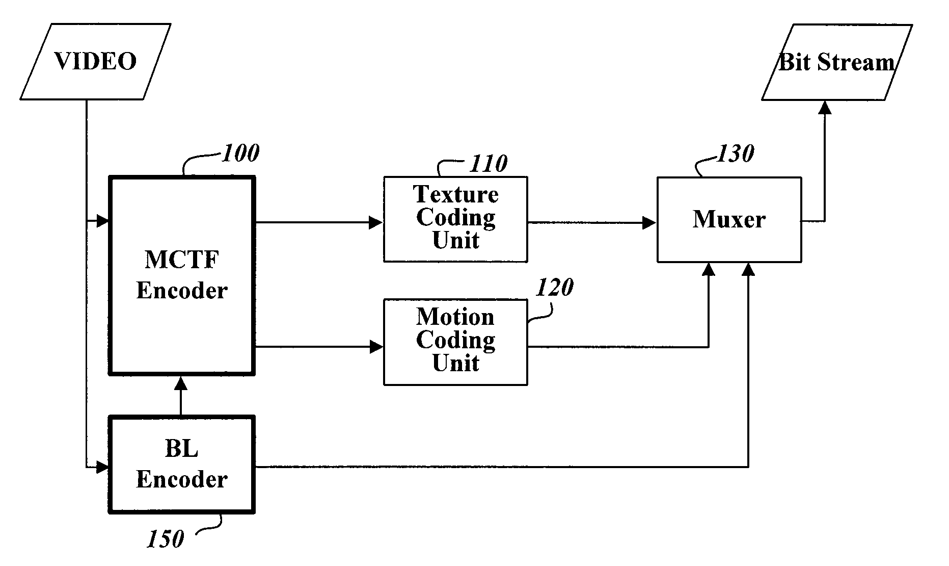
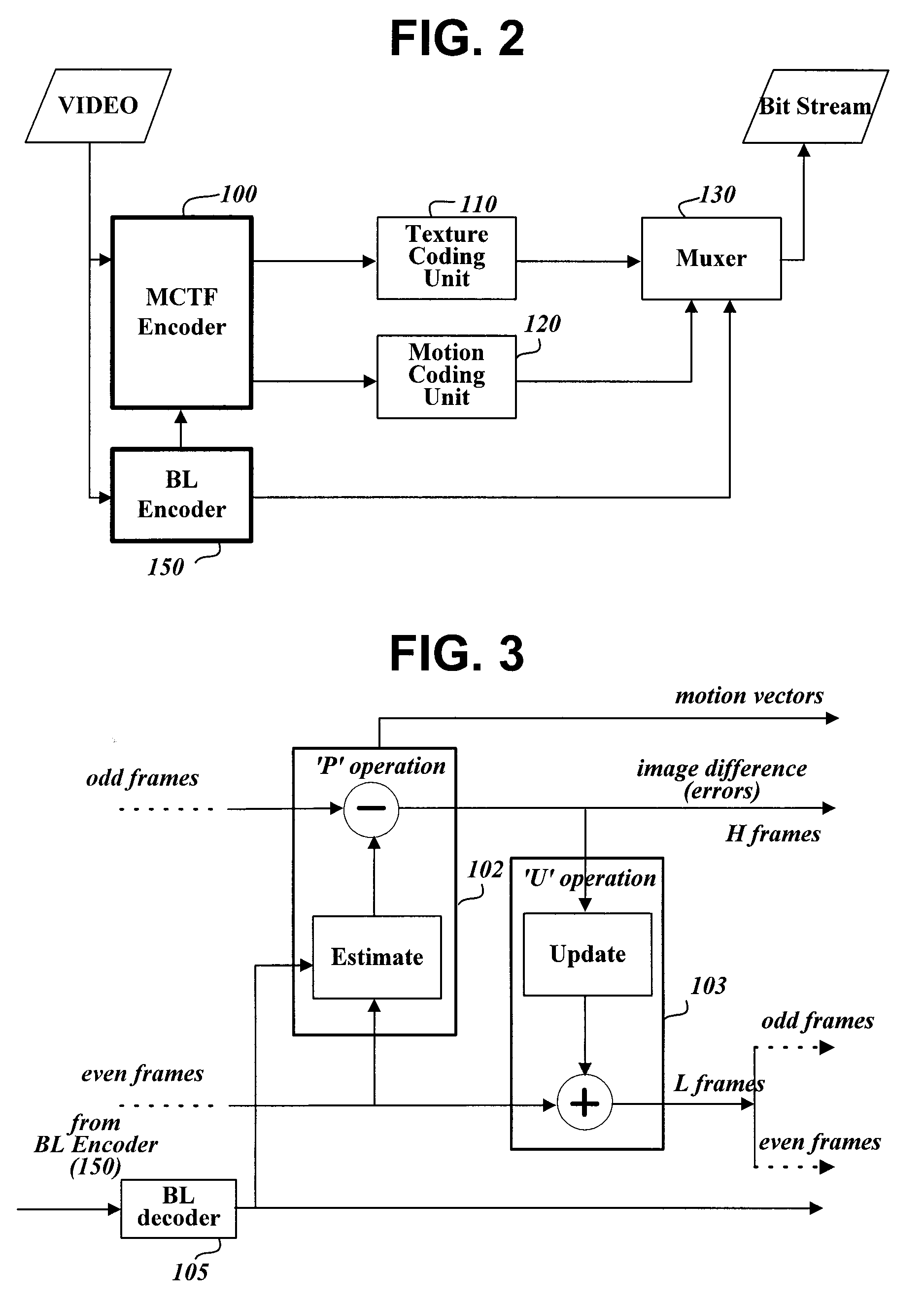
[0036]FIG. 2 is a block diagram showing the construction of a video signal encoding apparatus to which a method of scalably coding a video signal is applied, according to the present invention.

[0037]The video signal encoding apparatus of FIG. 2 of the present invention includes a Motion Compensated Temporal Filter (MCTF) encoder 100 for encoding an input video signal in macroblocks using an MCTF method and generating suitable management information, a texture coding unit 110 for transforming information about each encoded macroblock into a compressed bit stream, a motion coding unit 120 for coding the motion vectors of image blocks, obtained by the MCTF encoder 100, into a compressed bit stream using a preset method, a base layer encoder 150 for encoding the input video signal using a preset method, for example, MPEG 1, 2 or 4, or H.261, H.263 or H.264, and gen...


PUM


Abstract

The present invention relates to a method that uses a motion vector of a predictive video frame of a sub-layer to encode a video signal and decode encoded video data. The method encodes a video signal using a preset method to a bit stream of a base layer while encoding the video signal using a scalable MCTF method to a bit stream of an enhanced layer. When an arbitrary frame of the video signal is encoded, information, enabling at least one vector, derived from a first motion vector of a first block included in the bit stream of the base layer in the same direction as the first motion vector, to be used as a motion vector of an image block in the arbitrary frame, is recorded in the bit stream of the enhanced layer. The first motion vector is directed in the same direction as a temporal direction from the arbitrary frame to the first block.

Description

1. TECHNICAL FIELD[0001]The present invention relates, in general, to the scalable encoding and decoding of a video signal and, more particularly, to a method and apparatus that uses a motion vector of a base layer picture at the time of scalably coding a video signal based on a motion compensated temporal filter, and decodes video data encoded using the motion vector.2. BACKGROUND ART[0002]It is difficult to assign a wide bandwidth, such as the bandwidth required for television (TV) signals, to digital video signals that are transmitted in a wireless manner through mobile phones or notebook computers, which are currently widely used, or through mobile TVs or hand-held Personal Computers (PCs), which will be widely used in the future. Therefore, a standard to be used in a video compression scheme for such mobile devices needs to have higher video signal compression efficiency.[0003]Moreover, such mobile devices inevitably have varying inherent capabilities of processing or presentin...

Claims


Application Information

Patent Timeline
Patent Type & Authority Applications(United States)
IPC IPC(8): H04N7/24H04N7/26
CPCH04N19/52H04N19/176H04N19/46H04N19/513H04N19/615H04N19/63H04N19/61H04N19/31H04N19/13H04N19/30H04N19/53
Inventor JEON, BYEONG MOONPARK, SEUNG WOOKPARK, JI HO
Owner LG ELECTRONICS INC
Why Eureka
Try Eureka