

Fuel cell system
- Summary
- Abstract
- Description
- Claims
- Application Information
AI Technical Summary
Benefits of technology
Problems solved by technology
Method used
Image

Examples
first embodiment
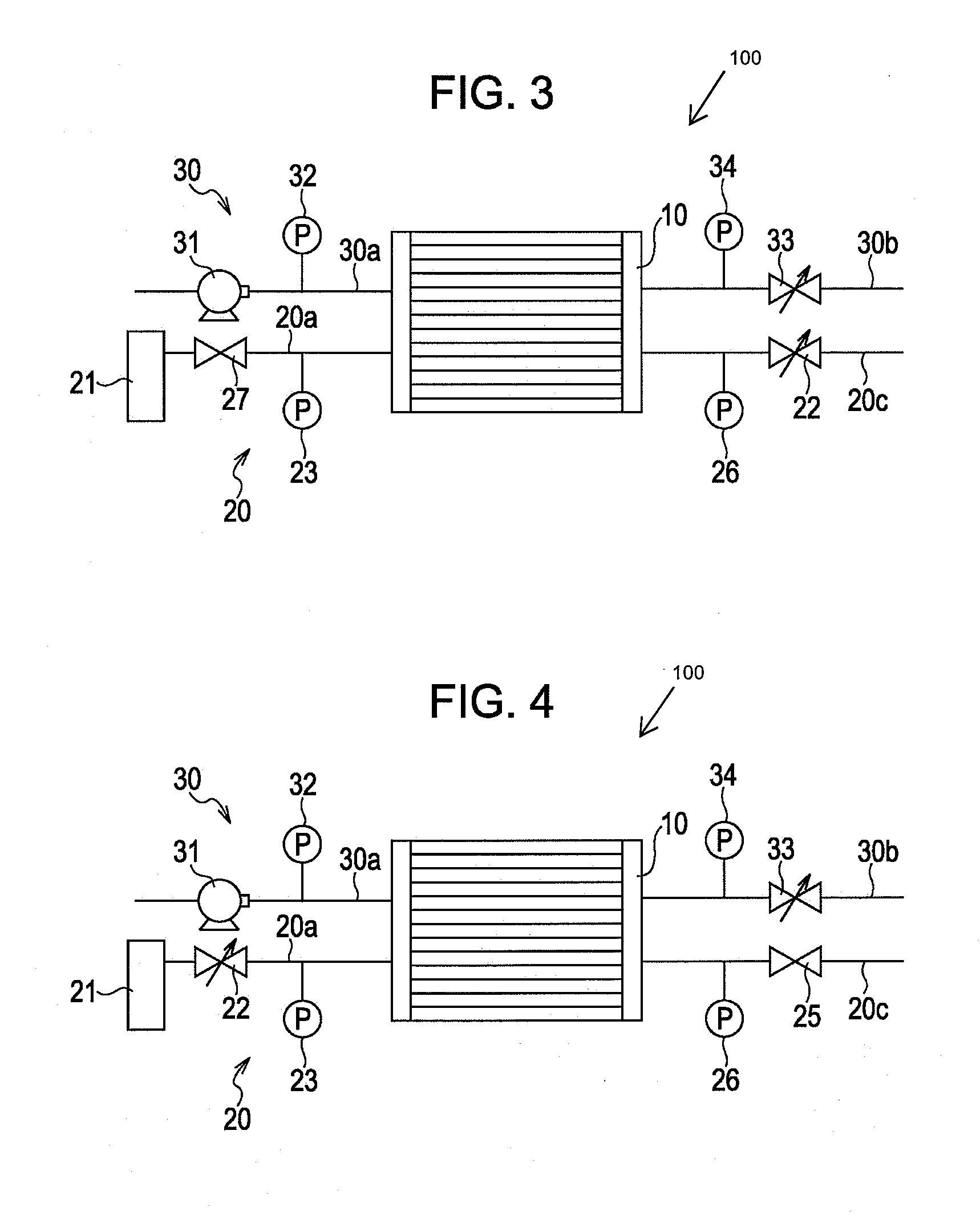
ation Process
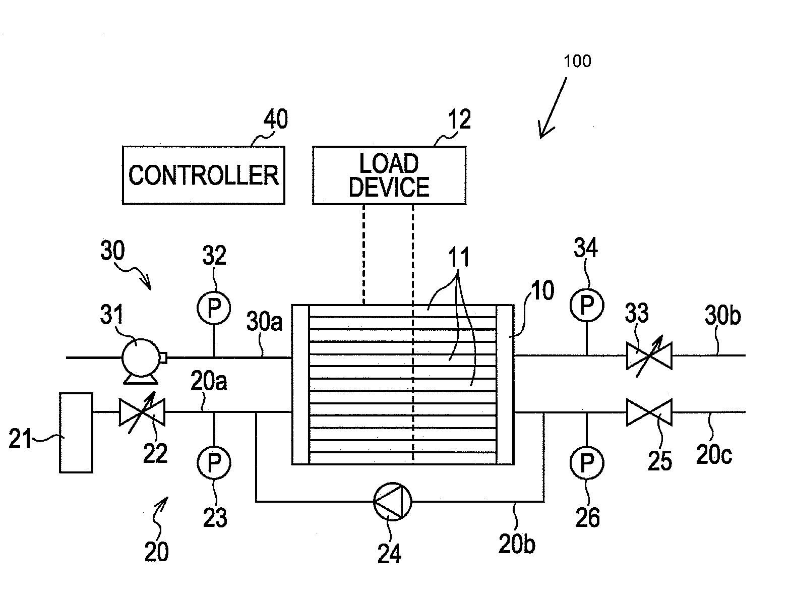
[0041]FIG. 5 is a functional block diagram illustrating the functional structure of the controller 40 as it relates to the leakage determination process. As shown in FIG. 5, the controller 40 includes a pressure-difference control unit 41, a leakage determination unit 42, and an operation control unit 43. The pressure-difference control unit 41 generates a pressure difference between the fuel electrode and the oxidizing electrode in each of the fuel cells 11 in the fuel cell stack 10 such that the pressure at the fuel electrode is higher than that at the oxidizing electrode. In addition, the pressure-difference control unit 41 changes the pressure difference with time. The leakage determination unit 42 determines the presence or absence of the leaking cell on the basis of the behavior of the cell voltages measured by the cell-voltage measuring devices 13 while the pressure difference between the fuel electrode and the oxidizing electrode is being increased with time by ...
embodiment
Advantages of Embodiment
[0063]As described in detail above, according to the fuel cell system of the present embodiment, the controller 40 monitors cell voltages while the pressure difference between the fuel electrode and the oxidizing electrode is increased with time in each of the fuel cells 11 included in the fuel cell stack 10. The controller 40 determines the presence or absence of a leaking cell based on the behavior of the monitored cell voltages. Therefore, the presence or absence of a leaking cell can be accurately determined in a short time. The present embodiment represents an improvement over the prior art systems, in which the presence or absence of a leaking cell is determined based on the behavior of cell voltages while the pressure difference is maintained constant. In particular, the following problems occur in the prior art process. When the pressure difference is maintained constant, the velocity of gas that flows from the fuel-electrode side to the oxidizing-ele...
second embodiment
[0068]A second embodiment of the present invention will now be described. According to the present embodiment, the timing at which the leakage determination process is performed by the controller 40 is optimized. The structure and operation of the fuel cell system according to the present embodiment are similar to those of the first embodiment. Therefore, only the characteristic parts of the present embodiment will be described below, and explanations similar to those of the first embodiment will be omitted.
[0069]In the fuel cell system according to the present embodiment, the controller 40 performs the leakage determination process in an activation overvoltage region.
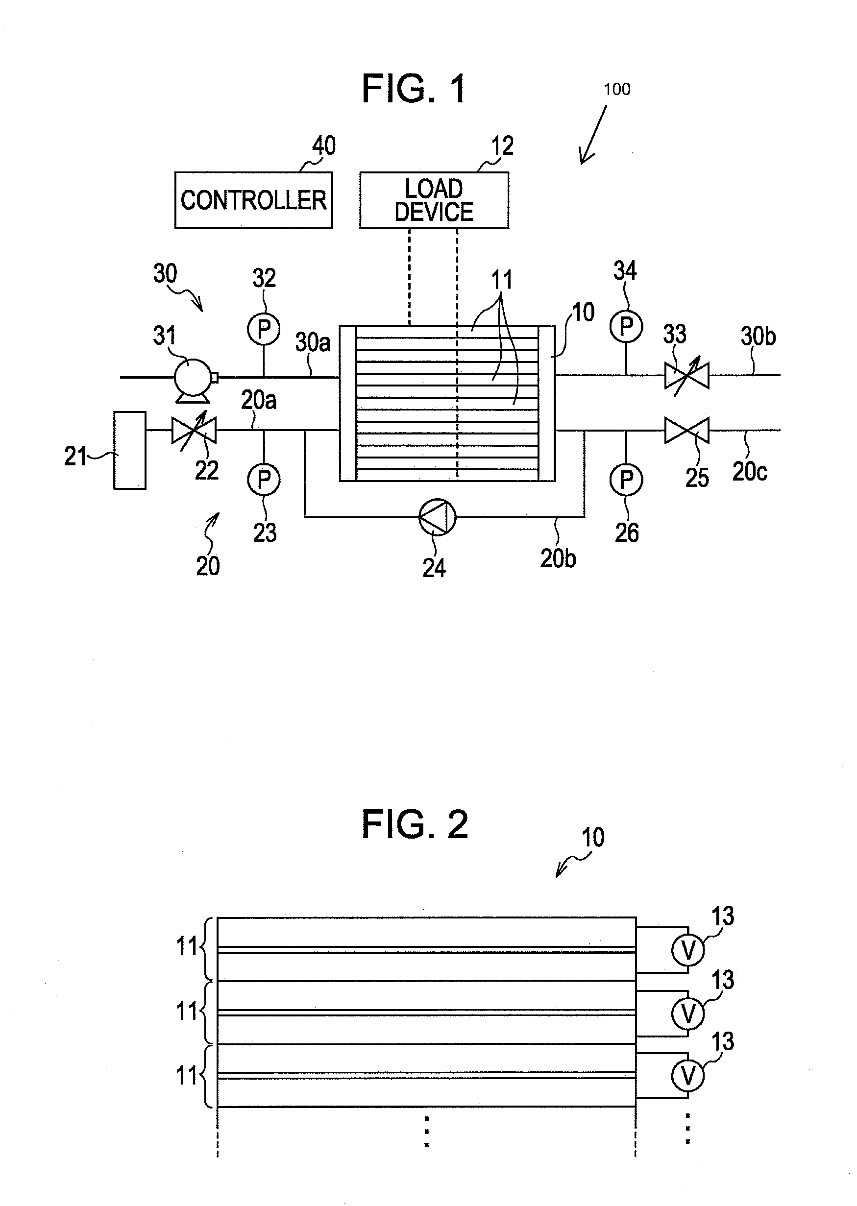
[0070]FIG. 11 is a characteristic diagram illustrating the relationship between the current and voltage in each of the fuel cells 11 included in the fuel cell stack 10. The slope of the current-voltage curve is termed the Tafel slope. In the state in which the fuel gas is supplied to the fuel electrode and the oxidizin...
PUM
 Abstract
Description
Claims
Application Information