Intraocular lens insertion tool

a technology for insertion tools and intraocular lenses, which is applied in the field of intraocular lens insertion tools, can solve the problems of not being able to permit the surgeon with the insertion tool, affecting the optical characteristics, and not being able to predict the insertion speed of the lens, so as to reduce the risk of possible damage to the center section of the intraocular lens, easy to set up the intraocular lens, and improve the effect of optical characteristics

Active Publication Date: 2009-07-02
KOWA CO LTD
View PDF14 Cites 46 Cited by
  • Summary
  • Abstract
  • Description
  • Claims
  • Application Information

AI Technical Summary

Benefits of technology

[0037]In the intraocular lens insertion tool constructed according to the present mode, by providing support to the outside peripheral section of the intraocular lens, the intraocular lens can be supported in a noncontact state with respect to its center section, which can affect the optical characteristics. The risk of possible damage to the center section of the intraocular lens can be reduced thereby. Moreover, when the intraocular lens is disposed resting on the resting face, the intraocular lens can be positioned resting on the resting face by a simple operation, namely, of removing the support member so that the outside peripheral support portions projecting up from the resting face retract below the resting face, allowing the surgeon to easily set up the int...

Problems solved by technology

However, an insertion tool like that disclosed in JP-B-07-079826 is merely a design adapted to increase the plunging speed of the plunger member in the approach zone, as such, it affords no particular advantages in relation to the lens insertion procedure per se.
This insertion tool is not capable of permitting the surgeon to carry out the lens ocular insertion procedure in the intended fashion.
Specifically, it is necessary for the surgeon to insert the lens into the eye at his or her own chosen speed, making it undesirable for a sudden change in perceived speed of pushing of the lens to occur at a moment just prior to pushing out the lens.
As a result, the intraocular lens may become pushed out at high speed be...

Method used


Image

  • Intraocular lens insertion tool
  • Intraocular lens insertion tool
  • Intraocular lens insertion tool

Examples


Embodiment Construction

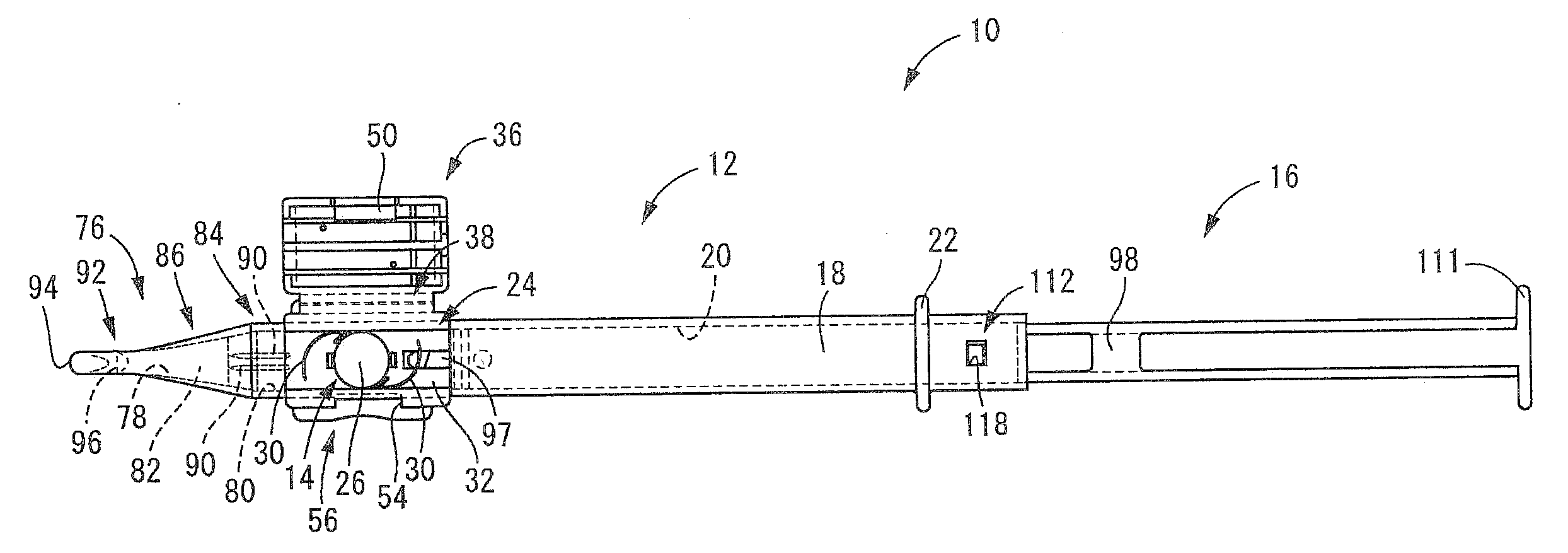
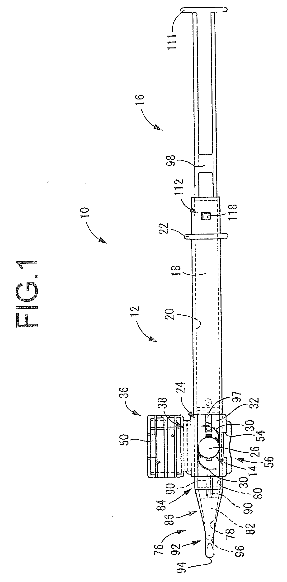
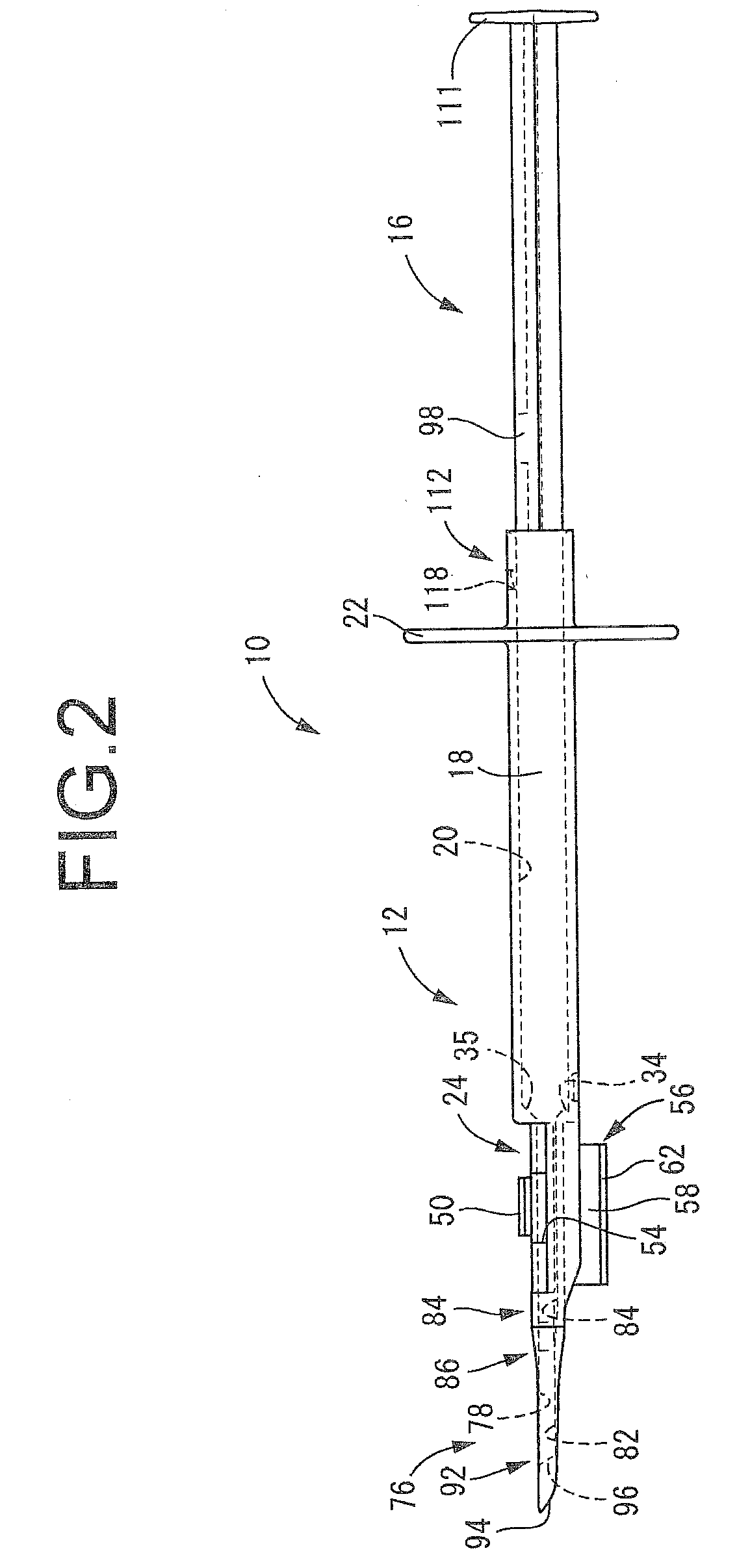
[0060]First, an intraocular lens insertion tool 10 according to a first embodiment of the present invention is depicted in FIGS. 1 and 2. The insertion tool 10 is adapted to accommodate an intraocular lens 14 in the interior of a tool body 12 having generally tubular shape perforated in its interior throughout its entire length and open at the front and back ends, into which inserts a plunger 16 serving as a plunger member. Herein, ‘front’ refers to the plunging direction of the plunger 16 (leftward in FIG. 1), and ‘upward’ refers to the upward direction in FIG. 2. ‘Left-right direction’ refers to the left-right direction of the insertion tool 10 in rear view (in FIG. 1, the upward direction is right and the downward direction is left).

[0061]To describe in greater detail, as depicted in FIGS. 3 to 6, the tool body 12 has a main tubular section 18 of generally tubular shape. A through-bore 20 is formed in the interior of the main tubular section 18 and with generally oblong cross sec...


PUM


Abstract

An intraocular lens insertion tool with a tool body for accommodating an intraocular lens and adapted to insert into an eye the intraocular lens through displacement of the lens in an axial forward direction by a plunging member, and to push out the lens through an insertion tube section disposed at an axial distal end of the tool body. The insertion tube section has an inclined orifice that opens on diagonal to the center axis of the insertion tube section. The plunger member has a sliding part that during displacement thereof in a direction of plunging into the tool body will slide against the tool body. A resistance graduating mechanism is provided for gradually increasing operation resistance of the plunger member by gradually increasing contact force on the sliding part as the lens gradually emerges from the inclined orifice through plunging of the plunger member into the tool body.

Description

INCORPORATED BY REFERENCE[0001]The disclosure of Japanese Patent Application No. 2007-341157 filed on Dec. 28, 2007 including the specification, drawings and abstract is incorporated herein by reference in its entirety.BACKGROUND OF THE INVENTION[0002]1. Field of the Invention[0003]The present invention relates to an intraocular lens insertion tool used to insert an intraocular lens into the eye.[0004]2. Description of the Related Art[0005]One method employed in the past in the field of cataract surgery involves extracting the intracapsular crystalline lens through a surgical incision made in ocular tissue such as the cornea (sclera) or anterior capsule section of the crystalline lens, and once the crystalline lens has been removed, inserting an intraocular lens serving as a replacement for the crystalline lens back through the incision and positioning it within the capsule.[0006]Particularly in recent years, methods that employ an intraocular lens insertion tool like that disclosed...

Claims


Application Information

Patent Timeline
IPC IPC(8): A61F9/007
CPCA61F2/1664A61F2/167
Inventor TANAKA, MASAYOSHI
Owner KOWA CO LTD
Why Eureka
Try Eureka