Angular rate sensor

Inactive Publication Date: 2009-07-09
ROHM CO LTD
View PDF9 Cites 7 Cited by
  • Summary
  • Abstract
  • Description
  • Claims
  • Application Information

AI Technical Summary

Benefits of technology

[0014]The present invention has been made to solve the problem described above, and aims to provide an angular rate sensor capable of reducing a parasitic capacitance between a detecting electrode and a driving electrode while largely vibrating a vibrator on a detecting electrode side.
[0015]Moreover, the present invention has been made to solve the problem described above, and aims to provide an angular rate sensor whose ability to detect an angular rate can be easily improved.
[0026]According to the present invention, the beam part is supported at the both ends, the detecting electrode is formed from one end of the beam part, and the driving electrode is formed from the other end of the beam part so as to be spaced from the detecting electrode. Thus, a parasitic capacitance between the detecting electrode and the driving electrode can be reduced. Moreover, when the vibrator is vibrated by the driving electrode, the vibration is easily transmitted to the detecting electrode side. Thus, the vibrator can be largely vibrated.
[0027]Moreover, according to the present invention, by providing the resonance frequency regulator at the front end of the detector in the vibrator, the resonance frequency regulator being capable of regulating the resonance frequency of the detector, the resonance frequencies in the width and thickness directions of the entire vibrator can be regulated. Thus, regardless of the width and thickness of the entire vibrator, a ratio of resonance frequencies of the entire vibrator is optimized by the resonance frequency regulator. Accordingly, the ability to detect the angular rate can be easily improved.

Problems solved by technology

The piezoelectric vibrator has a problem of a difficulty in largely vibrating the detection-side vibration branches.
For this reason, there are constraints on improvement in the detection ability of the vibrator by setting the thickness and width of the vibrator to be equal to each other, and thus it is difficult to improve the detection ability in that manner.
Furthermore, considering future miniaturization of the vibrator and reduction in the thickness of the film, there is a problem that it is more difficult to improve the detection ability of the vibrator by adjusting the width and thickness of the vibrator.

Method used


Image

  • Angular rate sensor
  • Angular rate sensor
  • Angular rate sensor

Examples


first embodiment

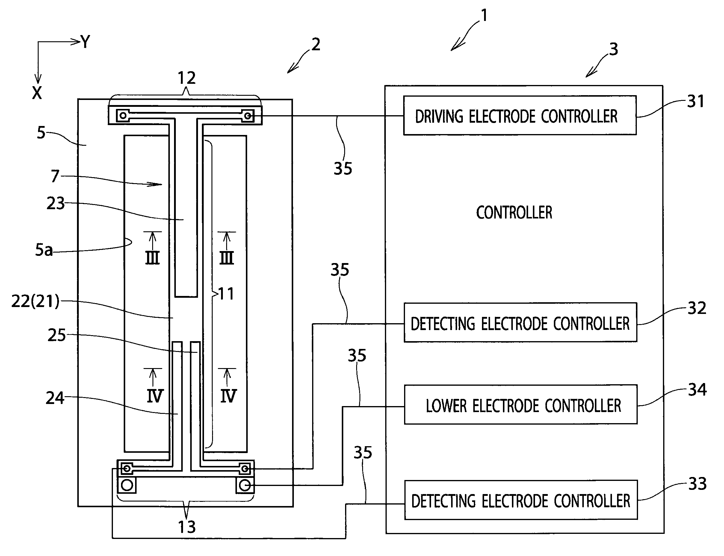
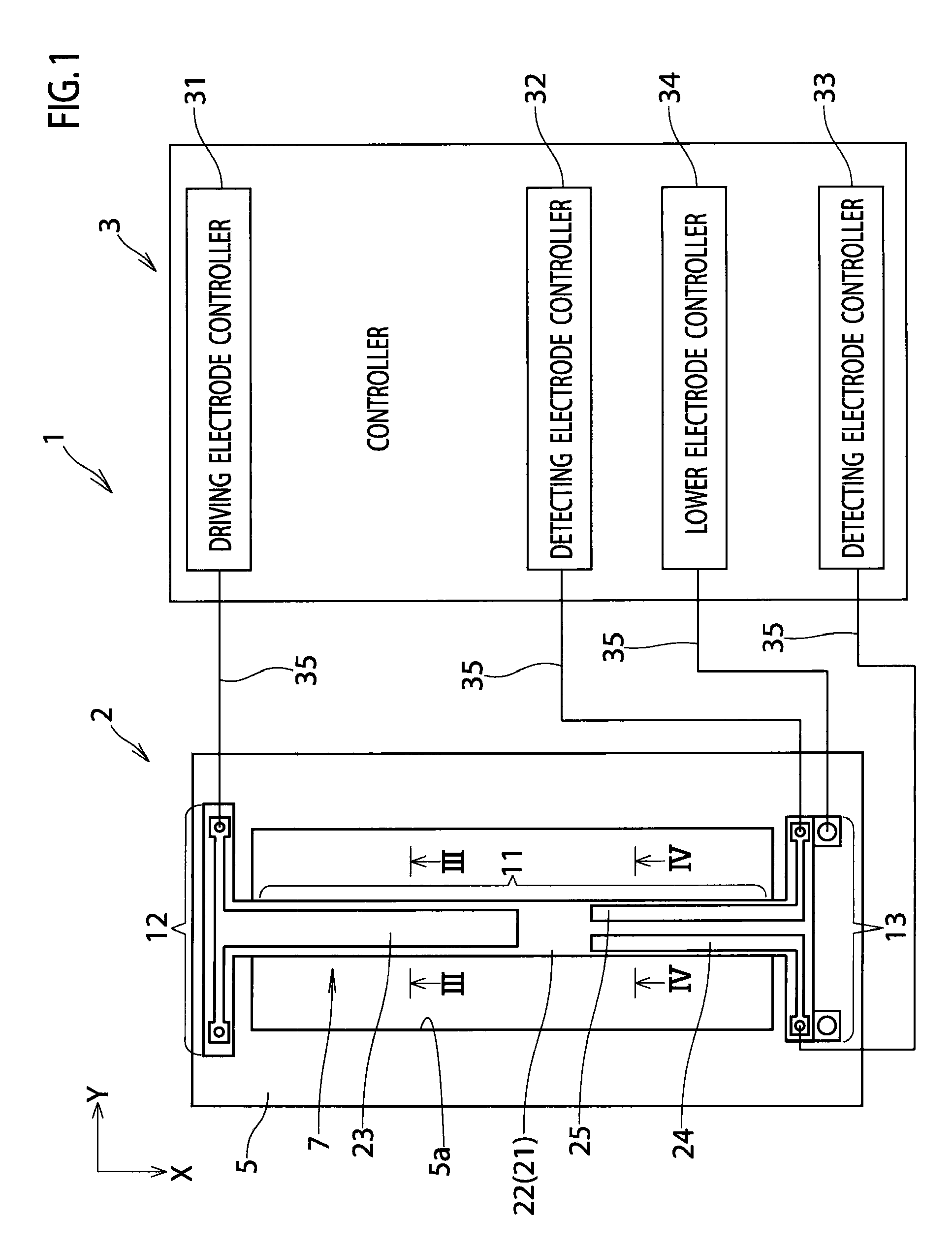
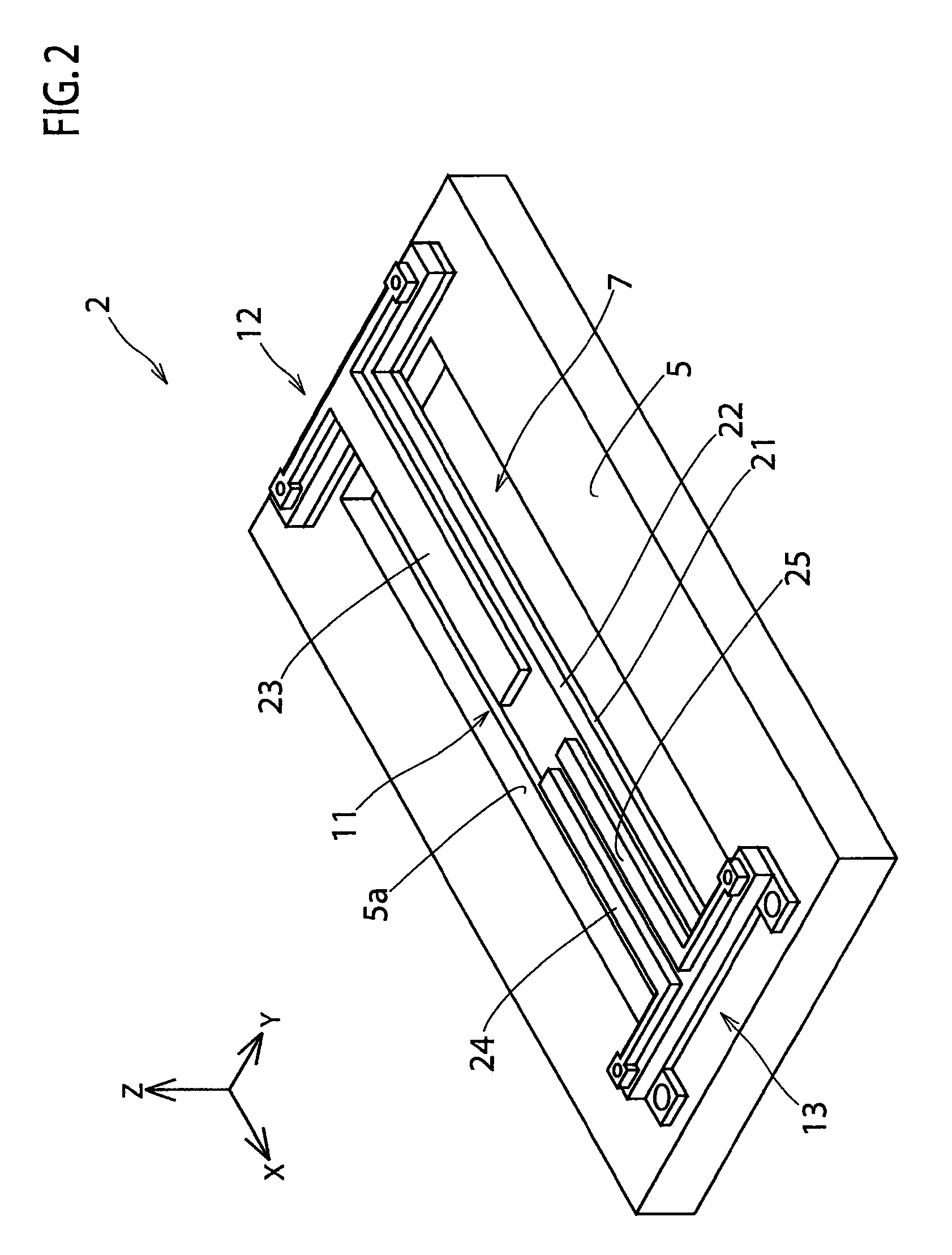
[0061]With reference to the drawings, a first embodiment of the present invention will be described below. FIG. 1 is a schematic overall diagram of an angular rate sensor according to the first embodiment. FIG. 2 is a perspective view of an element unit. FIG. 3 is a cross-sectional view taken along the line III-III in FIG. 1. FIG. 4 is a cross-sectional view taken along the line IV-IV in FIG. 1.

[0062]As shown in FIG. 1, an angular rate sensor 1 according to the first embodiment includes an element unit 2 and a controller 3.

[0063]As shown in FIGS. 1 to 4, the element unit 2 includes a semiconductor substrate 5, a lower protective film 6, a vibrator 7 and an upper protective film 8. Note that the lower protective film 6 and the upper protective film 8 are omitted in FIGS. 1 and 2.

[0064]The semiconductor substrate 5 is made of silicon having a thickness of about 300 μm. The thickness of the semiconductor substrate 5 can be accordingly changed as long as the thickness allows the substra...

second embodiment

[0093]Next, with reference to the drawings, description will be given of a second embodiment in which the vibrator according to the first embodiment is partially modified. FIG. 11 is a plan view of an element unit according to the second embodiment. FIG. 12 is a perspective view of the element unit. Note that the same components as those of the first embodiment are denoted by the same reference numerals and description thereof will be omitted.

[0094]As shown in FIGS. 11 and 12, an element unit 2A includes a semiconductor substrate 5 and a vibrator 7A. Note that the element unit 2A has a lower protective film and an upper protective film for protecting the vibrator 7A, as in the case of the first embodiment. However, those protective films are omitted in FIGS. 11 and 12.

[0095]The vibrator 7A includes a beam part 11 and a pair of supports 12A and 13A.

[0096]Both ends of the supports 12A and 13A are formed on the semiconductor substrate 5. Meanwhile, center portions of the supports 12A a...

third embodiment

[0098]Next, with reference to the drawings, description will be given of a third embodiment in which the vibrator according to the second embodiment is partially modified. FIG. 13 is a plan view of an element unit according to the third embodiment. FIG. 14 is a perspective view of the element unit. Note that the same components as those of the above embodiments are denoted by the same reference numerals and description thereof will be omitted.

[0099]As shown in FIGS. 13 and 14, an element unit 2B includes a semiconductor substrate 5 and a vibrator 7B. Note that the element unit 2B has a lower protective film and an upper protective film for protecting the vibrator 7B, as in the case of the first embodiment. However, those protective films are omitted in FIGS. 13 and 14.

[0100]The vibrator 7B includes a beam part 11 and a pair of supports 12B and 13B.

[0101]Both ends of the supports 12B and 13B are formed on the semiconductor substrate 5. Meanwhile, center portions of the supports 12B a...


PUM


Abstract

An angular rate sensor includes: a substrate; and a vibrator having a beam part supported in a state of floating from the substrate and a pair of supports formed on the substrate and provided at both ends of the beam part for supporting the beam part. The vibrator includes a piezoelectric film formed in the beam part, a detecting electrode for detecting an angular rate, the detecting electrode being formed on the piezoelectric film so as to extend toward a center portion of the beam part from one end thereof, and a driving electrode for vibrating the vibrator, the driving electrode being formed on the piezoelectric film so as to extend toward the center portion of the beam part from the other end thereof and to be spaced from the detecting electrode.

Description

CROSS REFERENCE TO RELATED APPLICATIONS AND INCORPORATION BY REFERENCE[0001]This application is based upon and claims the benefit of priority from prior Japanese Patent Application P2007-334015 filed on Dec. 26, 2007, prior Japanese Patent Application P2008-015374 filed on Jan. 25, 2008, and prior Japanese Patent Application P2008-313435 filed on Dec. 9, 2008, the entire contents of which are incorporated by reference herein.BACKGROUND OF THE INVENTION[0002]1. Field of the Invention[0003]The present invention relates to an angular rate sensor including a piezoelectric film.[0004]2. Description of the Related Art[0005]There has heretofore been known an angular rate sensor including a piezoelectric film and having an MEMS (Micro Electro Mechanical Systems) structure.[0006]Japanese Patent Application Publication No. Hei 9-178492 (hereinafter Patent Document 1) discloses a piezoelectric vibrator including a piezoelectric vibration element, two driving electrodes and two detecting electr...

Claims


Application Information

Patent Timeline
IPC IPC(8): G01P3/44G01C19/56G01C19/5656G01C19/5663
CPCG01C19/5656
Inventor TAKAOKA, MASAKIKAMINISHI, DAISUKEFUJIMORI, YOSHIKAZU
Owner ROHM CO LTD
Why Eureka
Try Eureka