Spring-operated Anti-stall tool

a spring-operated, anti-stall technology, applied in the direction of drilling pipes, rotary drilling, borehole/well accessories, etc., can solve the problems of motor stall, severe restriction of downhole fluid path, and dramatic increase of surface pump pressure, so as to maintain wob, reduce wob, and increase wob

Active Publication Date: 2009-07-09
WWT NORTH AMERICA HLDG
View PDF43 Cites 25 Cited by
  • Summary
  • Abstract
  • Description
  • Claims
  • Application Information

AI Technical Summary

Benefits of technology

[0010]Briefly, this invention comprises an anti-stall tool positioned in a downhole assembly near the bottom of the tubing adjacent a positive displacement motor (PDM) and the drill bit. In one embodiment, the tubing comprises a coiled tubing, although the tubing also can comprise rotary drilling tubing. The anti-stall tool controls the force applied to the drill bit during drilling to prevent the bit from stalling under load. The working pressure range of the PDM is sensed during use by a hydraulic valve control system and is used as an input to the controller. The controller alters weight-on-bit (WOB) if the downhole pressure goes beyond either end of the working pressure range of the system. The controller keeps the drill bit rotating by (1) maintaining WOB during normal drilling operations, (2) increasing WOB if sensed working pressure indicates that drill bit loading is low, and (3) reducing WOB which reduces PDM back-pressure to retract the drill bit from the bottom if excessive working pressure is sensed due to increased torque at the PDM.
[0011]The anti-stall tool generally comprises one or more hydraulic cylinders for applying an axial force either in a forward direction or a reverse direction. The controller comprises a system of hydraulic valves adapted to control piston force in either the forward or reverse directions. An active stage of the anti-stall tool reacts to the PDM producing low downhole pressures (e.g. below a pre-set low pressure) by actuating one or more of the pistons in the downhole direction to increase WOB which reduces PDM back-pressure. When the PDM is operating within its normal operating pressure range, the controller locks the pistons in a passive mode, in which the pistons are sealed and the anti-stall tool transfers force from the tubing to the drill bit. If the controller senses a pre-set high pressure or greater due to high torque at the PDM, the valve system reverses hydraulic flow to the pistons, which reduces WOB to force the drill bit away from the bottom to reduce PDM back-pressure.
[0012]One embodiment of the invention comprises an anti-stall method for controlling drilling operations in a downhole assembly which includes a tubing that extends downhole, a drill bit carried on the tubing, a positive displacement motor (PDM) for rotating the drill bit, and an anti-stall tool adjacent the PDM. The method comprises sensing pressure in the PDM, providing a range of operating pressures for the PDM defined by high and low limits of operating pressures, and operating the anti-stall tool in: (1) an active stage for increasing WOB forces in the downhole direction when the low limit of operating pressure is sensed, (2) a reverse stage for providing a WOB force in the reverse direction when the high limit of operating pressure is sensed, and (3) an optional passive stage in which the anti-stall tool is locked to transfer WOB directly from the tubing to the drill bit when the PDM is operating within the limits of its normal operating pressure range.
[0013]One embodiment of the invention comprises a spring-operated anti-stall tool adapted for use in a downhole assembly which comprises a tubing for extending downhole, a drill bit carried on the tubing, and a positive displacement motor (PDM) adjacent the drill bit for rotating the drill bit during drilling operations. A spring-operated anti-stall tool is carried on the tubing and positioned adjacent the PDM for preventing stalling of the PDM due to excessive loads on the drill bit. The spring-operated anti-stall tool comprises at least one piston in a cylinder having a forward piston area and a reverse piston area, and a controller comprising a hydraulic valve system for controlling operation of the piston. The forward piston area receives hydraulic fluid to produce a force in the downhole direction. The reverse piston area contains a load spring adapted to apply an upward spring force on the piston. The controller adjusts WOB in response to sensed PDM sets operating pressure. A controller input a desired range of operating pressures for the PDM, including an upper limit and a lower limit. The controller is adapted to: (1) supply hydraulic fluid to the forward piston area to increase WOB force in the downhole direction when operating pressure in the PDM surpasses the lower limit; this compresses the load spring as the piston moves in the downhole direction; (2) vent the piston volume in the forward piston area so the compressed spring will push the tool uphole, to reduce WOB when operating pressure in the PDM exceeds the upper limit; and (3) optionally lock the piston in a passive state when the PDM is operating within its normal operating pressure range.
[0014]These and other aspects of the invention will be more fully understood by referring to the following detailed description and the accompanying drawings.

Problems solved by technology

If the resistance increases to a condition which prohibits the PDM from rotating (i.e. excessive WOB), a motor stall is encountered.
During a motor stall, the motor stops turning, the downhole fluid path is severely restricted, and the surface pump pressure dramatically increases.
This event can eventually cause a motor failure, which requires the drilling process to be stopped, and the coiled tubing to be fatigue-cycled as the bit is pulled off bottom and run back into the hole to start drilling again.

Method used


Image

  • Spring-operated Anti-stall tool
  • Spring-operated Anti-stall tool
  • Spring-operated Anti-stall tool

Examples


Embodiment Construction

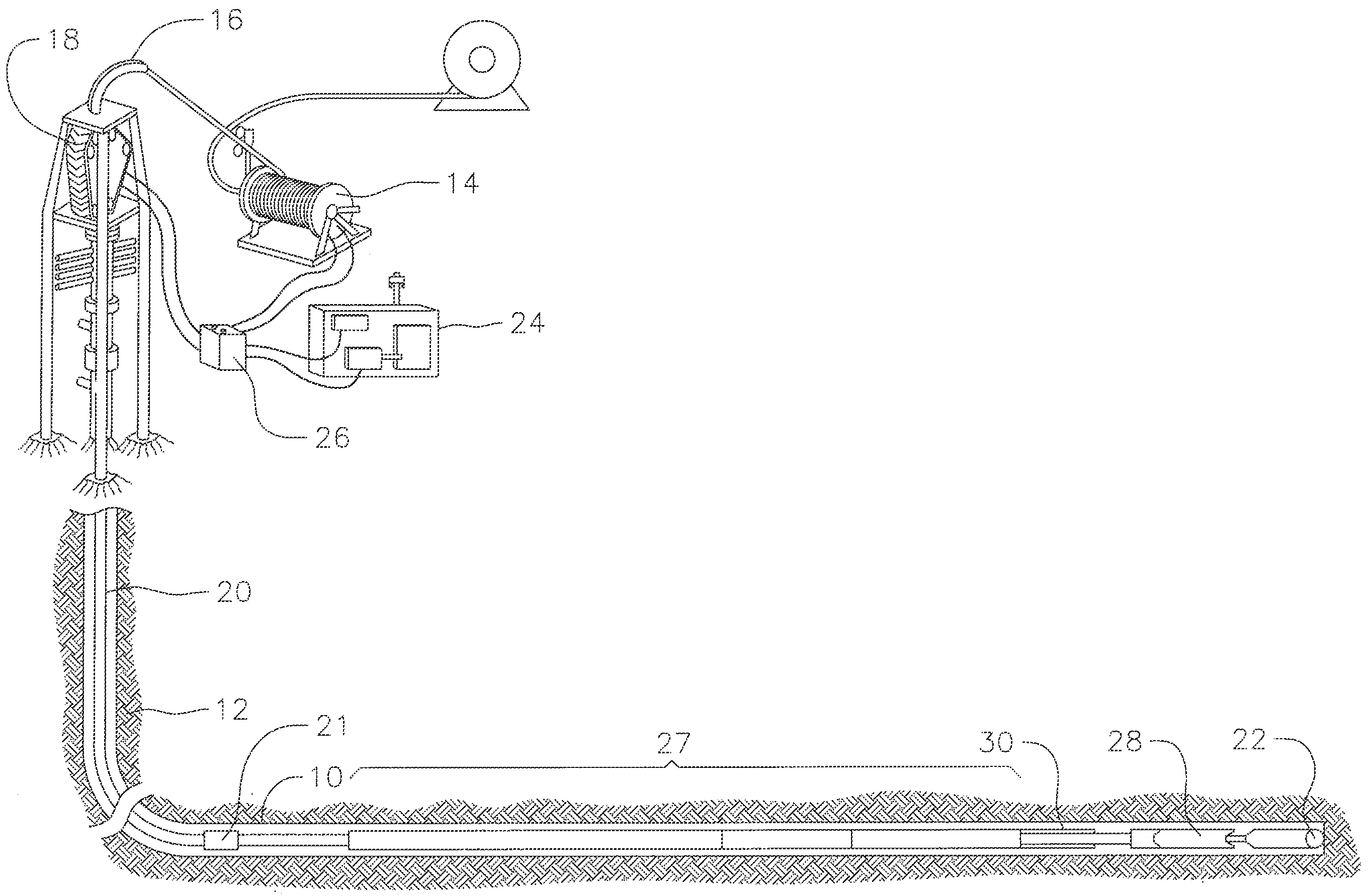
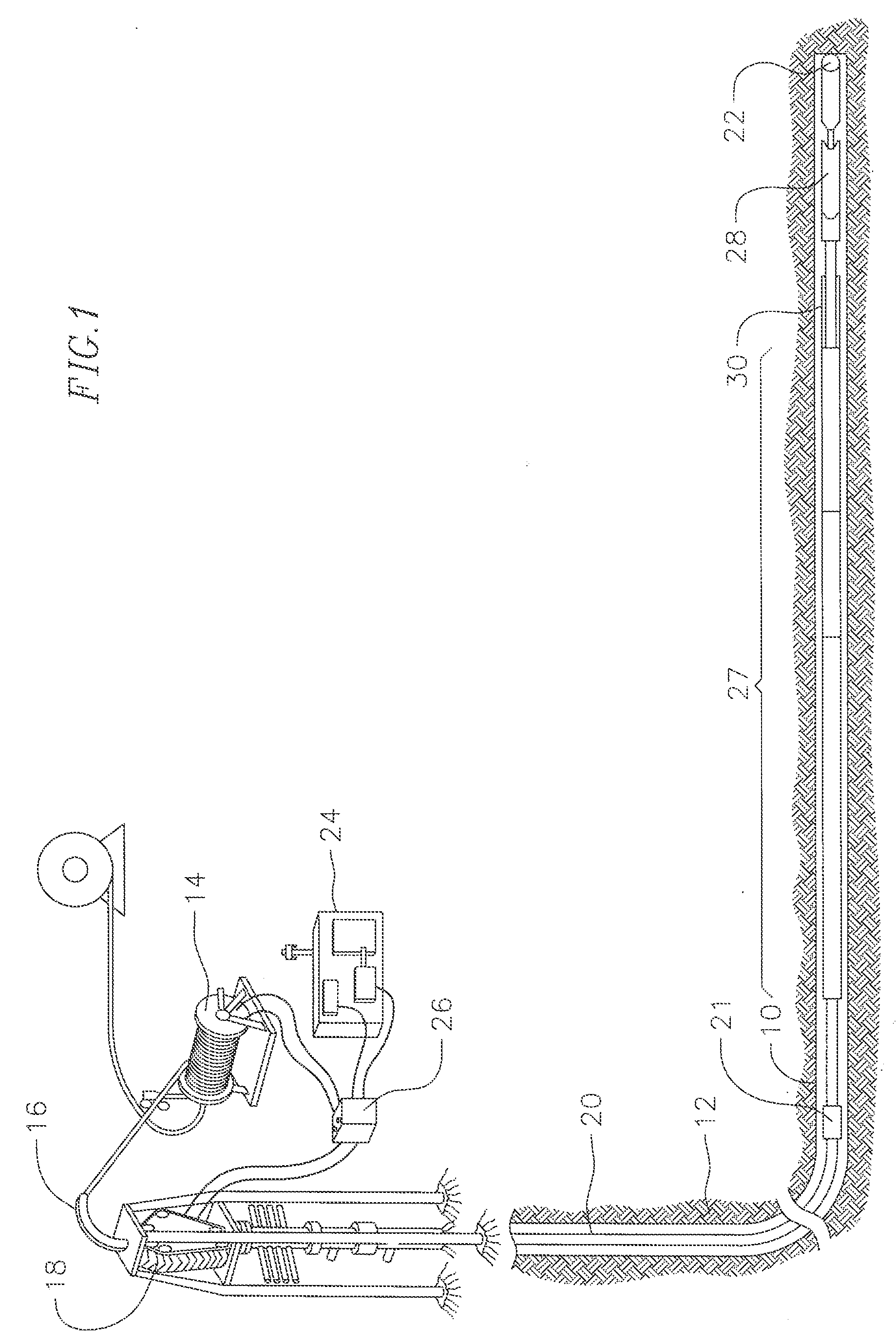
[0018]FIG. 1 is a schematic diagram illustrating a coiled tubing drilling system for drilling a well bore in an underground formation. The coiled tubing drilling system can include a coiled tubing reel 14, a gooseneck tubing guide 16, a tubing injector 18, a coiled tubing 20, a coiled tubing connector 21, and a drill bit 22 at the bottom of the well bore. FIG. 1 also shows a control cab 24, a power pack 26, and an alignment of other BHA tools at 27. A tractor (not shown), such as that described in U.S. Pat. No. 7,343,982, may be used to move downhole equipment within the bore. The '982 patent is incorporated herein in its entirety by this reference. During drilling, the downhole equipment includes a downhole motor 28, such as a positive displacement motor (PDM), for rotating the drill bit. A spring-operated anti-stall tool (AST) 30, according to principles of this invention, is positioned near the bottom of the coiled tubing, upstream from the downhole motor and the drill bit. In on...


PUM


Abstract

An anti-stall tool in an oil well drilling assembly that controls reciprocation of the drill bit by controller that alters weight-on-bit (WOB) depending upon measured downhole pressure or torque. The downhole controller keeps the drill bit rotating by maintaining WOB during normal drilling operations, increasing WOB if sensed working pressure indicates that drill bit loading or torque is undesirably low, and reversing WOB by applying a spring force for retracting the drill bit if excessive working pressure or torque is sensed.

Description

CROSS-REFERENCE[0001]This application claims the priority date of U.S. Provisional Applications 61 / 009,972, filed Jan. 3, 2008, and 61 / 082,931, filed Jul. 23, 2008, which are incorporated herein in their entirety by this reference.FIELD OF THE INVENTION[0002]This invention relates to downhole drilling assemblies, and more particularly, to a spring-operated anti-stall tool for controlling weight on-bit during drilling operations.BACKGROUND[0003]Coiled tubing drilling requires the use of a downhole positive displacement motor (PDM) to rotate the drill bit. During drilling operations, the unloaded PDM rotates at a constant RPM and achieves a “freespin” motor pressure, with respect to the fluid flow rate. As the drill bit encounters the bottom of the hole and force is transferred to the bit, referred to as weight-on-bit (WOB), the motor will sense an increase in torque. The increase in torque is a result of increased resistance to rotating at the constant RPM (assuming a constant flow r...

Claims


Application Information

Patent Timeline
Patent Type & Authority Applications(United States)
IPC IPC(8): E21B44/06E21B7/00E21B44/00
CPCE21B44/005E21B44/06E21B44/04E21B44/00
Inventor MOCK, PHILIP WAYNEKRUEGER, IV, RUDOLPH ERNST
Owner WWT NORTH AMERICA HLDG
Why Eureka
Try Eureka