Electrical controller for Anti-stall tools for downhole drilling assemblies and method of drilling optimization by downhole devices

a technology of electric controller and anti-stall tool, which is applied in the direction of drilling rods, drilling pipes, rotary drilling, etc., can solve the problems of motor stall, severe restriction of downhole fluid path, and dramatic increase in surface pump pressure, so as to eliminate the effects of bending, differential pressure and weight-on-bit, and enhance future drilling operations

Inactive Publication Date: 2016-03-31
WWT NORTH AMERICA HLDG
View PDF2 Cites 25 Cited by
  • Summary
  • Abstract
  • Description
  • Claims
  • Application Information

AI Technical Summary

Benefits of technology

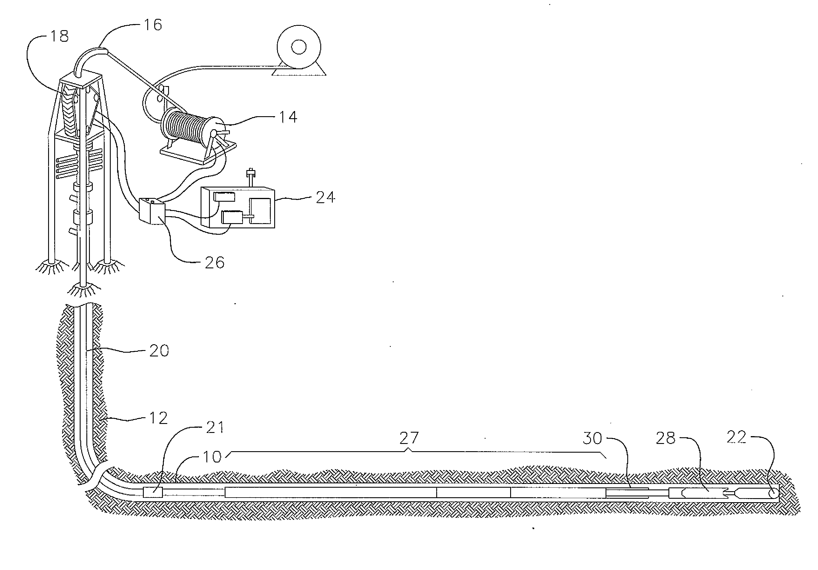
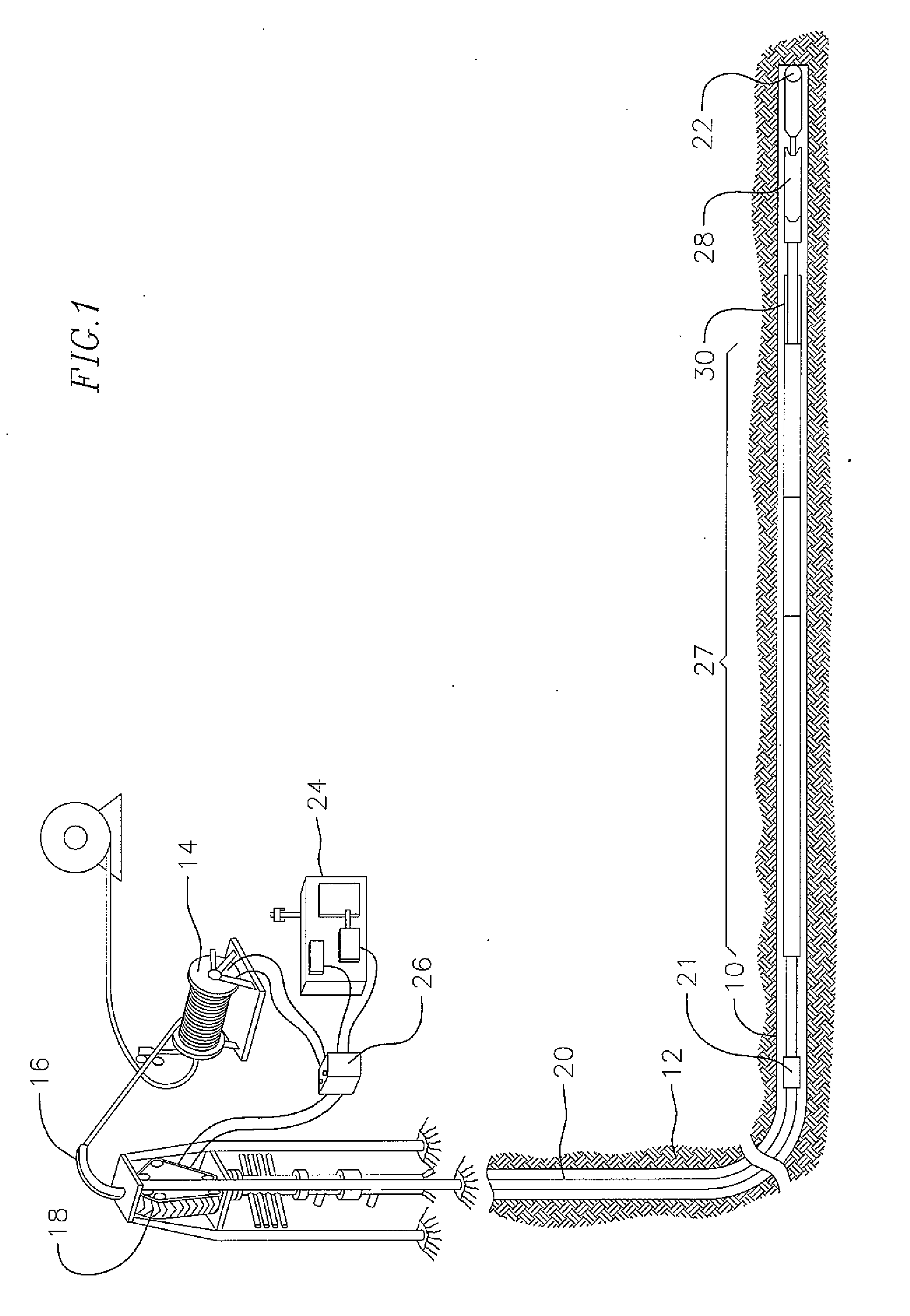
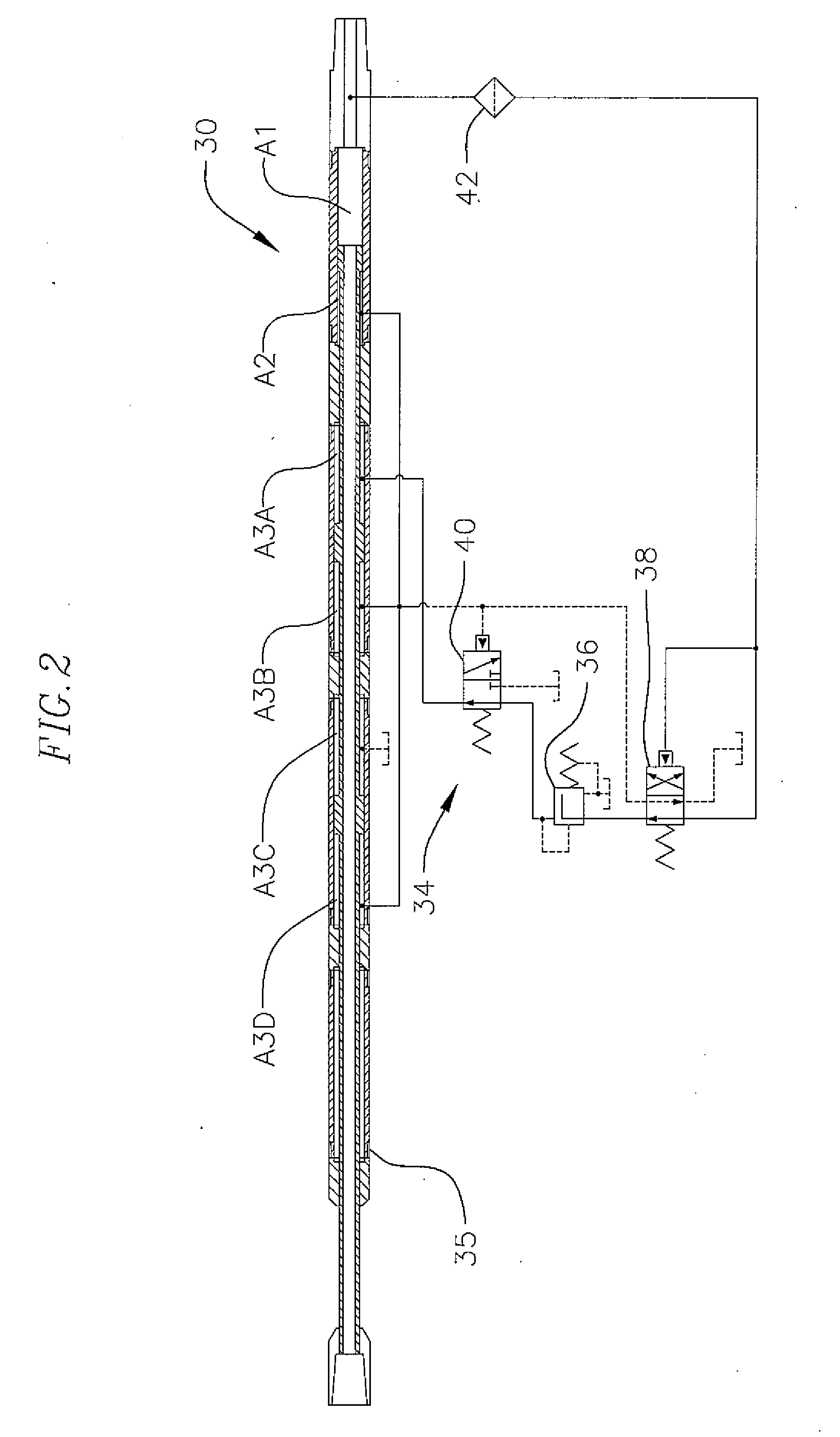
[0015]Briefly, the invention comprises an electrical controller for an anti-stall tool for use in a downhole assembly near the bottom of the tubing adjacent a positive displacement motor (PDM) and the drill bit. In one embodiment, the tubing comprises a coiled tubing, although the invention also can be used in rotary drilling applications. The electrical controller controls the force applied to the drill bit during drilling to prevent the drill bit from stalling under load. A working pressure range of the PDM is sensed during use by a hydraulic valve control system and is used as an input to the controller. The controller alters weight-on-bit (WOB) if the downhole pressure goes beyond either end of a preset working pressure range of the system. The controller keeps the drill bit rotating by (1) maintaining WOB during normal drilling operations, (2) increasing WOB if sensed PDM working pressure indicates that drill bit loading is low, and (3) reducing WOB which reduces PDM back-pressure to retract the drill bit from the bottom if excessive working pressure is sensed due to increased torque at the PDM.

Problems solved by technology

If the resistance increases to a condition which prohibits the PDM from rotating (i.e. excessive WOB), a motor stall is encountered.
During a motor stall, the motor stops turning, the downhole fluid path is severely restricted, and the surface pump pressure dramatically increases.
This event can eventually cause a motor failure, which requires the drilling process to be stopped, and the coiled tubing to be fatigue-cycled as the bit is pulled off bottom and run back into the hole to start drilling again.
There are several inherent limitations of current drilling systems.
First, they rely on surface measurements and surface equipment manipulation to control the downhole interaction of the bit and the formation.
Second, the use of downhole equipment for measurements contain a time delay from instrumentation measurement to operator response which also assumes the operator knows the correct response.
Lastly, current drilling systems require significant expense and training, equipment and system monitoring of the process to maximize its efficiency.
Consequently, the current limitations allow for downhole parameters to exceed the operational limitations and result in tool failures.
One significant source of the problems associated with non-productive time (NPT) is the failure of positive displacement motors (PDM) also referred to as mud motors.
The failures are a result of the PDM exceeding the operational envelope and stalling.
These issues eventually cause the rubber stator of the PDM to wear, resulting in poor performance or failure.
Another significant problem with drilling, especially in deep water offshore wells is stick-slip.
Stick-slip is erratic changes in the downhole RPM of the drilling assembly.
Rotary steerable tools are subject to premature failure when exposed to significant stick-slip.
The fundamental problem with this concept is the lack of operational functionality and variability.
However, other factors such a fluid properties, plugged nozzles, and worn motor components can also effect the back pressure.
Once downhole, any change in the fluid system or any change in the tools causing back pressure, will alter the system environment and render the tool inoperable.

Method used


Image

  • Electrical controller for Anti-stall tools for downhole drilling assemblies and method of drilling optimization by downhole devices
  • Electrical controller for Anti-stall tools for downhole drilling assemblies and method of drilling optimization by downhole devices
  • Electrical controller for Anti-stall tools for downhole drilling assemblies and method of drilling optimization by downhole devices

Examples


example

[0094]Specifications for One Embodiment AST illustrated in FIGS. 6-8:

DescriptionCharacteristicTool OD3.00inTool ID.75inLength - Expanded8.1ftLength - Collapsed7.4ftStroke9inMax Temp300°F.Tensile Strength50,000lbsMax Motor Torque2,000ft-lbsMax Dog Leg25° / 100ftTool Joint2⅜PAC

[0095]The design of an electrically controlled AST is flexible in that the pressure settings may be changed to fine tune the AST. Programmable pressure settings may be changed on surface or while in operation. Current available communication techniques include mud pulse telemetry, fiber optic and wireline.

[0096]If a large increase in WOB is needed, then the shaft of the AST can be replaced to allow the installation of additional pistons.

Total DownholePressure ControlMax WOB from# of PistonArea (sq. in)Valve Setting (psi)AST (lbs)14.86503,05527.96505,135311.06507,150

[0097]Features and Benefits:

[0098]The following illustrates features of an electrically controlled AST:[0099]Active WOB: The tool will attempt reset in...


PUM


Abstract

A method of operating a bottom hole assembly having a drill pipe, an anti-stall tool, a motor and a drill bit in real-time including entering an upper torque threshold and a lower torque threshold as operating parameters for the bottom hole assembly into the anti-stall tool, continuously sensing torque of the bottom hole assembly by a torque sensor in the bottom hole assembly, electronically determining if the sensed torque has exceeded the upper torque threshold or the lower torque threshold for a specified duration of time requiring an intervention by the anti-stall tool, and communicating instructions to the anti-stall tool for proper hydro-mechanical adjustment of the anti-stall tool.

Description

CROSS-REFERENCE TO RELATED APPLICATION(S)[0001]This application is a continuation-in-part of U.S. patent application Ser. No. 13 / 267,654, filed Oct. 6, 2011, which claims priority to and the benefit of U.S. Provisional Application No. 61 / 405,066, filed Oct. 20, 2010, the entire contents of which are incorporated herein by reference.BACKGROUND[0002]The present invention provides an improvement in anti-stall tool controllers, and more specifically is an electrical controller to operate an anti-stall tool (AST) and mechanical specific energy drilling systems for controlling weight-on-bit during drilling operations and a method of drilling optimization by use of downhole devices.[0003]Coiled tubing drilling requires the use of a downhole positive displacement motor (PDM) to rotate the drill bit. During drilling operations, the unloaded PDM rotates at a constant RPM and achieves a “freespin” motor pressure, with respect to the fluid flow rate. As the drill bit encounters the bottom of th...

Claims


Application Information

Patent Timeline
Patent Type & Authority Applications(United States)
IPC IPC(8): E21B44/04E21B3/00
CPCE21B3/00E21B44/04E21B4/02E21B44/06
Inventor MOCK, PHILIP, WAYNE
Owner WWT NORTH AMERICA HLDG
Why Eureka
Try Eureka