Electrical controller for Anti-stall tools for downhole drilling assemblies

US20120097451A1Inactive Publication Date: 2012-04-26WWT NORTH AMERICA HLDG
23 Cites 18 Cited by

Patent Information

Authority / Receiving Office
US · United States
Current Assignee / Owner
Publication Date
2012-04-26
Estimated Expiration
Not applicable · inactive patent

Smart Images

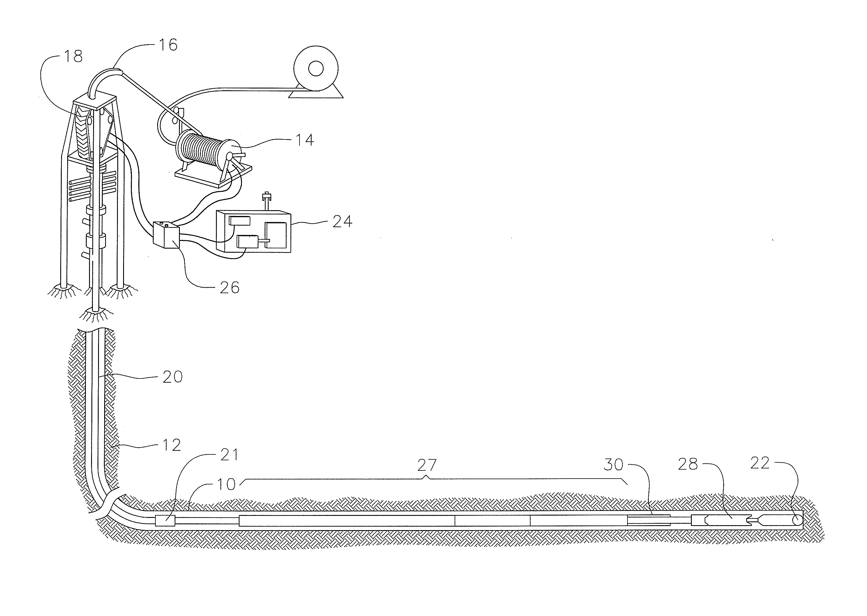
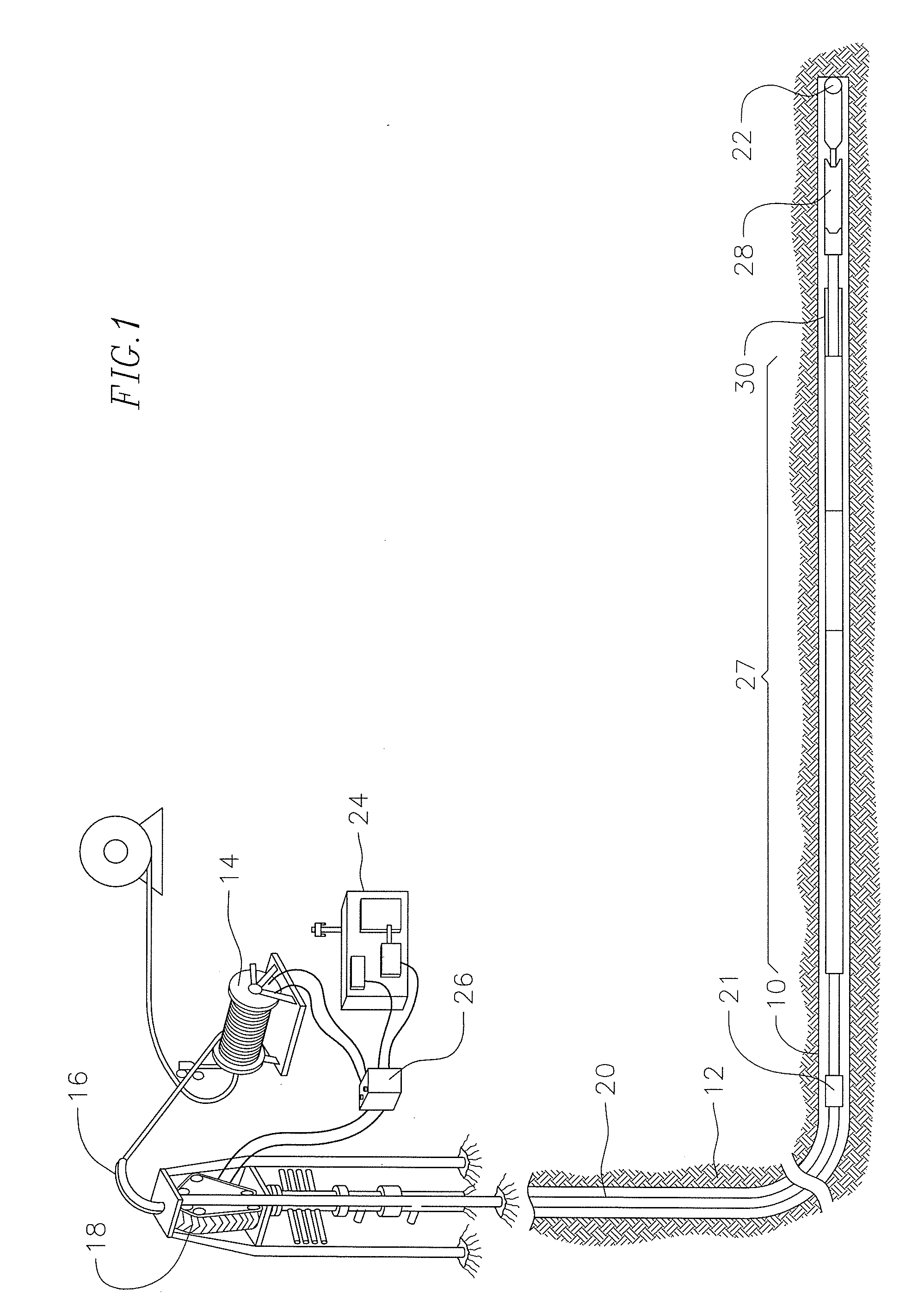
  • Figure 1
    Figure 1
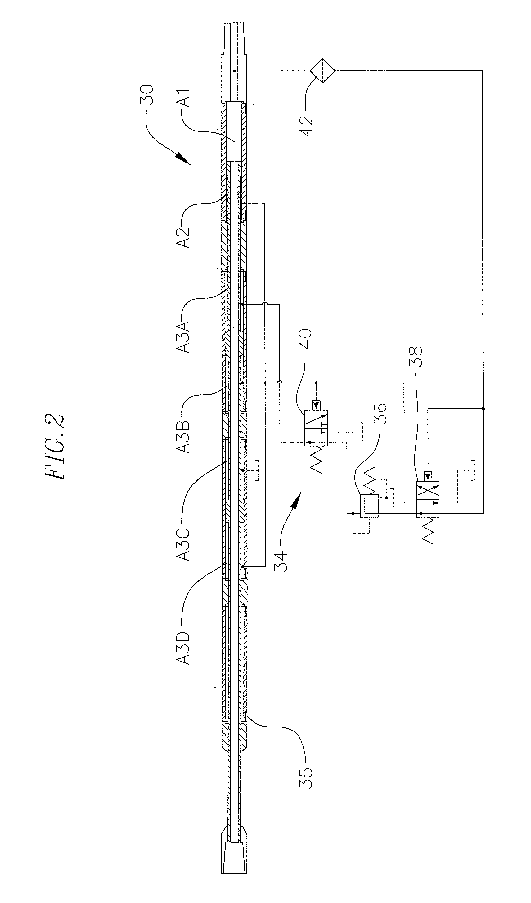
  • Figure 2
    Figure 2
  • Figure 3
    Figure 3
Patent Text Reader

Abstract

An anti-stall tool in an oil well drilling assembly that controls reciprocation of the drill bit by an electrical controller that alters weight-on-bit (WOB) depending upon measured downhole pressure or torque at the downhole motor. The electrical controller receives preset high and low working pressure limits for the downhole motor and activates a hydraulic valve system to keep the drill bit rotating by maintaining WOB during normal drilling operations, increasing WOB if sensed working pressure indicates that drill bit loading or torque is undesirably low, and reversing WOB by retracting the drill bit if excessive working pressure or torque is sensed.
Need to check novelty before this filing date? Find Prior Art

Description

CROSS-REFERENCE TO RELATED APPLICATION(S)

[0001] This application claims priority to U.S. Provisional Application No. 61 / 405,066, filed Oct. 20, 2010, which is incorporated herein by reference.BACKGROUND

[0002] The present invention provides an improvement in anti-stall tool controllers, and more specifically is an electrical controller to operate an anti-stall tool (AST) for controlling weight-on-bit during drilling operations.

[0003] Coiled tubing drilling requires the use of a downhole positive displacement motor (PDM) to rotate the drill bit. During drilling operations, the unloaded PDM rotates at a constant RPM and achieves a “freespin” motor pressure, with respect to the fluid flow rate. As the drill bit encounters the bottom of the hole and force is transferred to the bit, referred to as weight-on-bit (WOB), the motor will sense an increase in torque. This increase in torque is a result of increased resistance to rotating at the constant RPM (assuming a constant flow rate). In turn...

Examples

example

Specifications for One Embodiment AST Illustrated in FIGS. 6-8

[0076]

DescriptionCharacteristicTool OD3.00inTool ID.75inLength - Expanded8.1ftLength - Collapsed7.4ftStroke9inMax Temp300°F.Tensile Strength50,000lbsMax Motor Torque2,000ft-lbsMax Dog Leg25° / 100ftTool Joint2⅜PAC

[0077]The design of an electrically controlled AST is flexible in that the pressure settings may be changed to fine tune the AST. Programmable pressure settings may be changed on surface or while in operation. Current available communication techniques include mud pulse telemetry, fiber optic and wireline.

[0078]If a large increase in WOB is needed, then the shaft of the AST can be replaced to allow the installation of additional pistons.

Total DownholePressure ControlMax WOB from# of PistonArea (sq. in)Valve Setting (psi)AST (lbs)14.86503,05527.96505,135311.06507,150

[0079]Features and Benefits:

The following illustrates features of an electrically controlled AST:

[0080]Active WOB: The tool will attempt reset into the ...