Container for engine lubricating oil

a technology for engine lubricating oil and container, which is applied in the direction of container preventing decay, auxilary lubrication, lubricant transfer, etc., can solve the problems of oil itself deteriorating, oil deteriorating more rapidly, and more difficult to replace the oil in the system

Inactive Publication Date: 2009-07-09
PAPAS GARY R
View PDF12 Cites 16 Cited by
  • Summary
  • Abstract
  • Description
  • Claims
  • Application Information

AI Technical Summary

Benefits of technology

[0009]The oil tank connectors may be quick discon

Problems solved by technology

In a wet sump system, the integral nature of this type of system makes it more difficult to replace the oil in the system.
Further, the high heat from the engine can cause

Method used


Image

  • Container for engine lubricating oil
  • Container for engine lubricating oil
  • Container for engine lubricating oil

Examples


Embodiment Construction

[0032]Although the disclosure hereof is detailed and exact to enable those skilled in the art to practice the invention, the physical embodiments herein disclosed merely exemplify the invention which may be embodied in other specific structures. While the preferred embodiment has been described, the details may be changed without departing from the invention, which is defined by the claims.

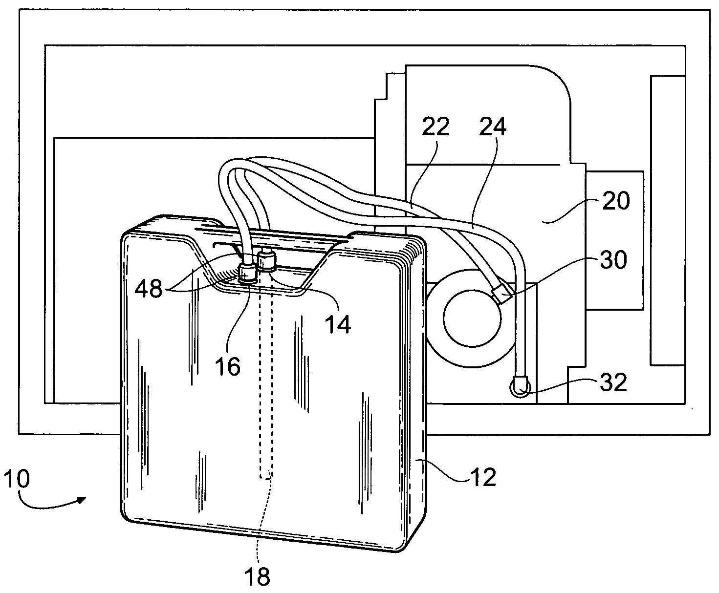
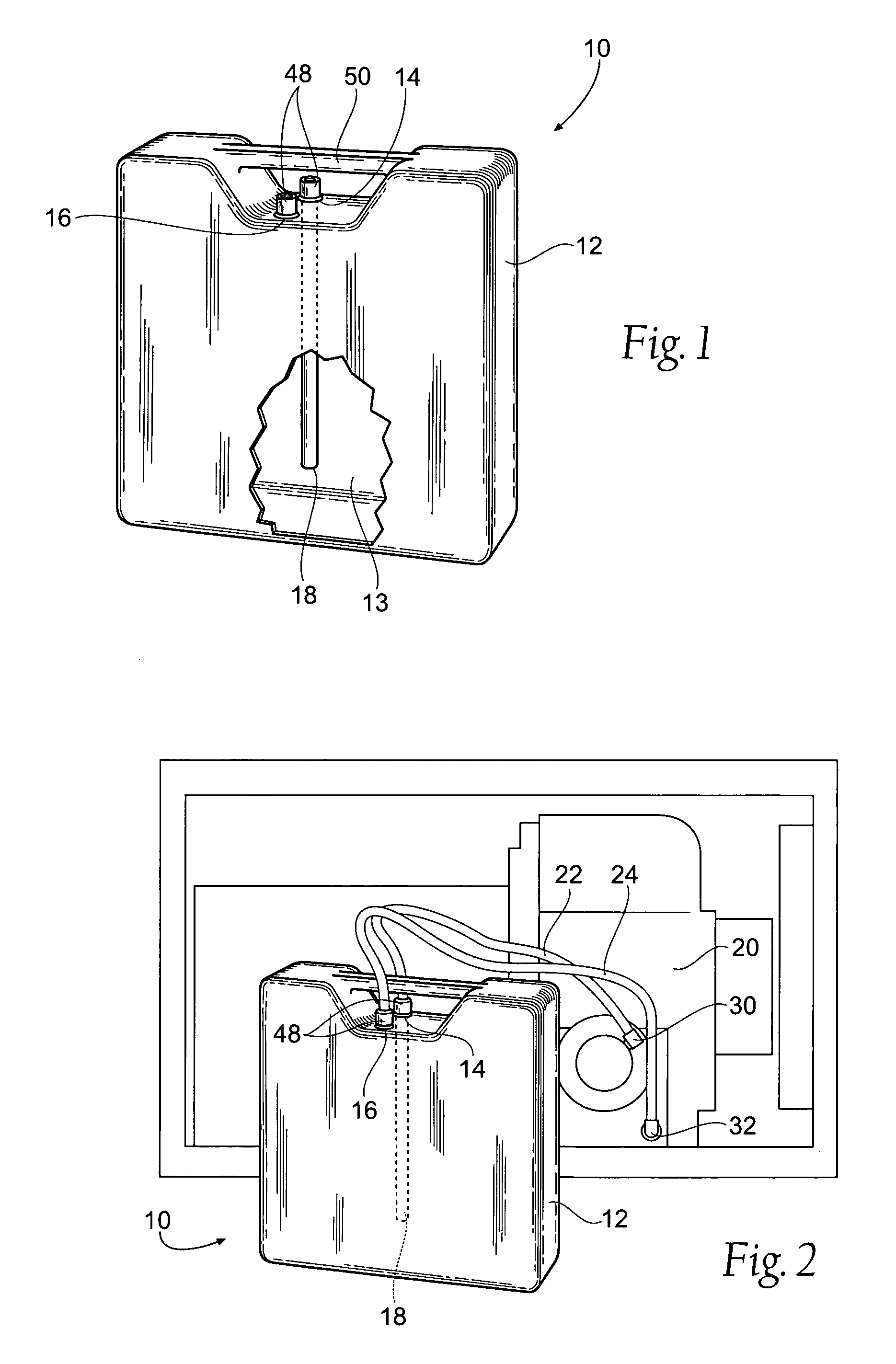
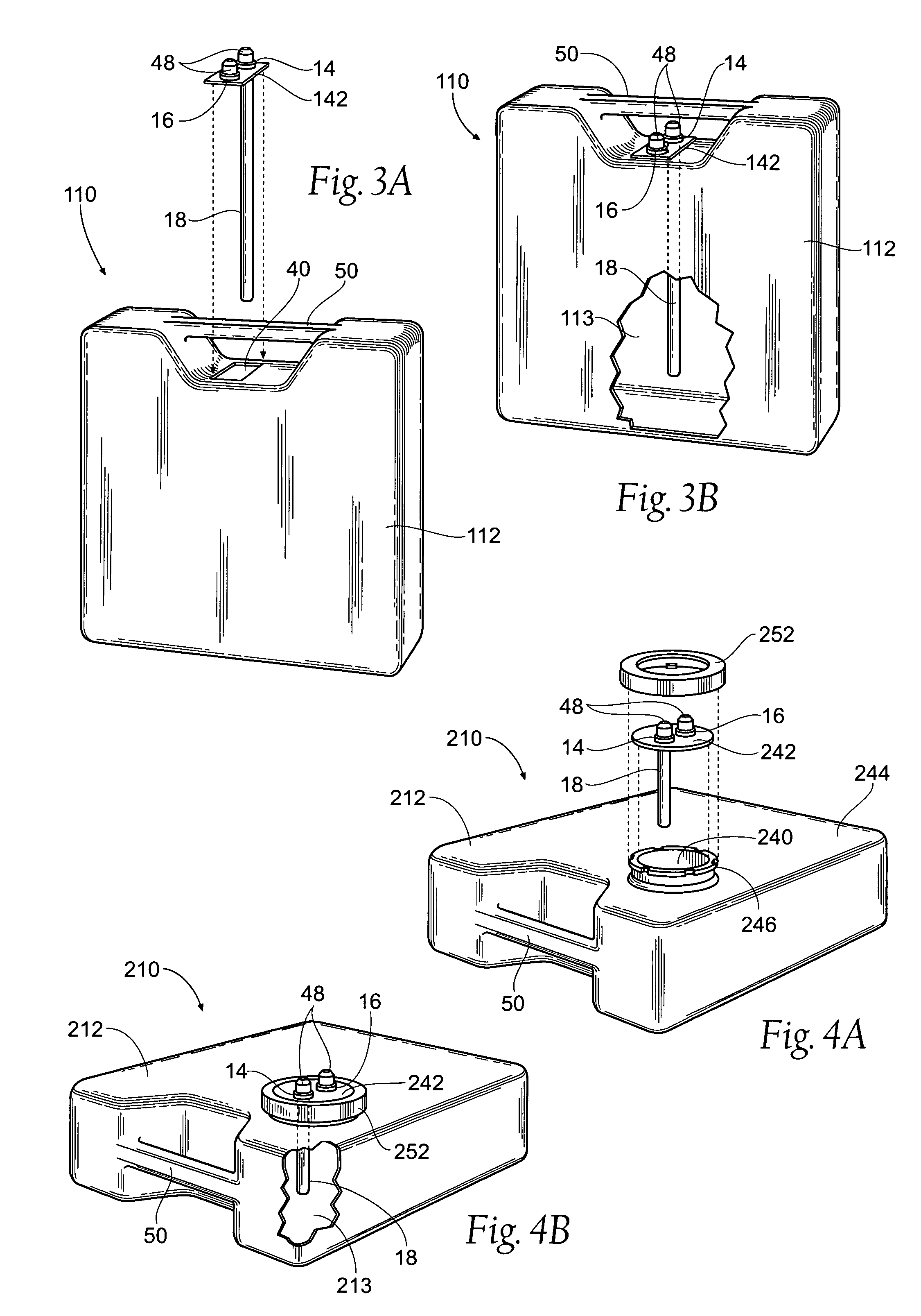
[0033]FIG. 1 shows a first embodiment of a lubricating oil tank 10 according to present invention. The oil tank 10 may be used in combination with an engine 20 as shown in FIG. 2. The oil tank 10 preferably comprises a body 12 forming a reservoir 13 for containing lubricating oil. In the illustrated embodiment, the body 12 is preferably generally rectangular; however it is contemplated that the body 12 could take virtually any shape. The oil tank body 12 preferably has two ports 14,16 on the top surface of the body 12. The first port is an outlet port 14 for oil exiting the tank 10 while the secon...


PUM


Abstract

A removable oil storage tank for lubricating an engine. The oil storage tank includes a body having a reservoir, an oil inlet and an oil outlet. A pick up tube in connected to the oil outlet. Connectors are coupled to the oil inlet and oil outlet. Oil lines are coupled to the connectors to couple to oil inlet of the tank to the outlet of the engine and the oil outlet of the tank to the inlet of the engine.

Description

BACKGROUND OF THE INVENTION[0001]The invention disclosed here in relates to an improved container for engine lubricating oil. There are two different types of lubrication systems, a wet sump and a dry sump. The standard engine lubrication system is a wet sump system. In a wet sump, the sump is permanently attached to the engine. An oil pan is located at the bottom forming the sump. Oil is pumped into the various components of the engine and is allowed to drain to the base of the engine, into the oil pan. From the oil pan the oil is pumped back up to the various components.[0002]In a wet sump system, the integral nature of this type of system makes it more difficult to replace the oil in the system. Further, the high heat from the engine can cause the oil itself to deteriorate. At higher temperatures acids form more quickly. The oil in the wet sump system is continuously churned up by the crankshaft of the engine which can cause the oil to deteriorate more rapidly. This is because of...

Claims


Application Information

Patent Timeline
IPC IPC(8): B65D25/28F01M1/12F01M11/02F16L15/00F16L37/00F16L23/00
CPCF16N37/00F01M11/04F01M2011/0483
Inventor PAPAS, GARY R.
Owner PAPAS GARY R
Why Eureka
Try Eureka