Water draining system for a fuel filter

a fuel filter and water draining system technology, applied in the direction of liquid fuel feeders, filtration circuits, water/sludge/sewage treatment, etc., can solve the problems of compartment draining, compartment draining, and many challenges, so as to reduce the likelihood of corrosion, reduce the current level, and reduce the space

Inactive Publication Date: 2009-07-09
PARKER HANNIFIN MFG (UK) LTD
View PDF9 Cites 20 Cited by
  • Summary
  • Abstract
  • Description
  • Claims
  • Application Information

AI Technical Summary

Benefits of technology

[0033]Combining the water sensor and valve in the same housing is advantageous over the prior art as this forms a more compact water drainage system which takes up relatively less space in the engine cavity.
[0034]Additionally, it has been found that reducing the level of current running through the sensors can substantially reduce the likelihood of corrosion after the tips come in contact with water. Hence, if the water level rises to the predetermined level and an operator is unable to drain the water from the reservoir within a relatively short period of time, reducing the current allows the driver additional time to have the reservoir drained without sustaining substantial damage to the water sensor.

Problems solved by technology

Drainage of water compartments can pose many challenges.
For example, if a water compartment does not have an easily visible water level indicator, a driver or mechanic is reduced to draining the compartment on a periodic basis, as there is no way of identifying when the compartment requires draining.
Draining on a periodic basis is very inaccurate and can result in the compartment being drained even though the process is not required.
Alternatively, if the water level rises at a greater rate than predicted, the compartment may become full and any additional water may not be filtered from the fuel.
This is problematic because if the filtration of water in an engine is inefficient, the water may work its way into the lubricated moving parts of an engine, and this will cause corrosion and unnecessary wear.
Whilst this apparatus does remove the need for periodic draining, the device is only effective so long as the driver remembers to physically check the water level and drain the compartment at the appropriate time.
Although this device overcomes the need for physically checking the water level of a filter system, a driver or mechanic is still required to physically drain the water compartment.
This can be problematic as quite often, due to space restrictions and awkward positioning of the drainage valve within the engine cavity, manual drainage can be a time consuming process.
Furthermore, if a driver is unable to drain the compartment themselves, the vehicle must be taken to a mechanic and hence the vehicle could be out of service for some time, depending on the availability of a mechanic.
Additionally, if the water sensor is the type which is activated by water coming into contact with a pair of metal sensor elements having a current running through them, the longer the sensors are in contact with the water, the higher the risk of corrosion.
Therefore, if the water filter can not be emptied within a relatively short period of time, the water sensor may need replacing.
Again, this may result in the vehicle being out of service for an unknown period of time, depending on the availability of parts and labour.

Method used


Image

  • Water draining system for a fuel filter
  • Water draining system for a fuel filter
  • Water draining system for a fuel filter

Examples


Embodiment Construction

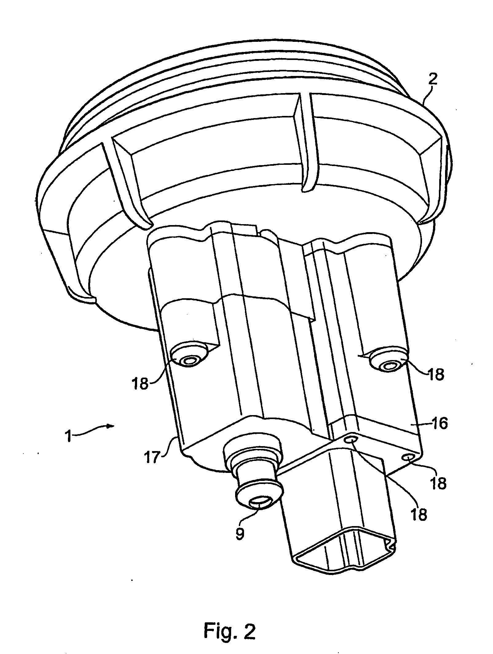
[0049]Referring to the drawings, the water draining system includes a housing 1 and a reservoir 2 mounted to the housing for collecting water from a fuel filter (not shown).

[0050]The housing includes a water sensor 3 with its distal end protruding into the reservoir 2 and its proximal end protruding into the housing 1. The proximal end is connected to a controller which is located either inside or outside the housing. The controller is connected to a power source, such as a battery.

[0051]In one embodiment, the water sensor includes a pair of sensing elements 4 having a voltage running therethrough. The distal tips of the sensing elements 4 protrude through one end of a sensor retaining module 5 and the proximal ends of the sensing elements 4 extend into the inner space of housing 1. The retaining module 5 prevents the un-exposed portion of the tips from coming in contact with any water contained in the reservoir 2.

[0052]Preferably, the reservoir 2 is coupled to one side of the housi...


PUM

PropertyMeasurementUnit
time periodaaaaaaaaaa
currentaaaaaaaaaa
currentaaaaaaaaaa

Abstract

A water draining system for a fuel filter having a water collecting reservoir is disclosed. The water draining system has a housing adapted for attachment to the reservoir, the housing having a water sensor arranged to protrude into the reservoir and having a valve with an inlet for draining water collected in the reservoir. The valve is selectively moveable between an open and a closed configuration. The water draining system also has a controller connected to the sensor such that when the water level in the reservoir reaches a predetermined level, the sensor sends a signal to the controller and movement of the valve between the open and closed configuration is directly or indirectly dependent upon subsequent signals generated by the controller.

Description

CROSS REFERENCE TO RELATED APPLICATIONS[0001]This application is a continuation of copending International Application No. PCT / GB2007 / 003137, filed Aug. 16, 2007, which designated the United States, the disclosure of which is incorporated herein by reference, and which claims priority to Great Britain Patent Application No. 0616465.1, filed Aug. 17, 2006.FIELD OF THE INVENTION[0002]The present invention relates to water draining systems for fuel filters. It has been developed primarily as a device for sensing and draining water collected in a fuel filter and will be described hereinafter with reference to this application. However, it will be appreciated that the invention is not limited to this particular field of use.BACKGROUND[0003]Fuel systems in automotive engines generally include a fuel filter system which removes water and other contaminants from fuel. It is common for primary fuel filters to have a water collecting compartment and a manually operable drainage valve.[0004]Dr...

Claims


Application Information

Patent Timeline
Patent Type & Authority Applications(United States)
IPC IPC(8): C02F1/461
CPCB01D36/005F02M37/221B01D36/006F02M37/28F02M37/24B01D36/00F02M37/22
Inventor FERRARI, LANACORE, PHIL
Owner PARKER HANNIFIN MFG (UK) LTD
Why Eureka
Try Eureka