Automatic Weld Arc Monitoring System

a welding system and arc data technology, applied in the field of automatic welding arc monitoring system, can solve the problems of increasing the complexity and expense of welding cell installation, insufficient training of welding personnel on the factory floor to properly identify and correct problems, and requiring additional external wiring for sensors

Active Publication Date: 2009-07-09
ILLINOIS TOOL WORKS INC
View PDF13 Cites 324 Cited by
  • Summary
  • Abstract
  • Description
  • Claims
  • Application Information

AI Technical Summary

Problems solved by technology

Increasingly, moreover, welding personnel on the factory floor are relatively inexperienced and insufficiently trained to properly identify and correct for these problems.
While providing a valuable function, these devices, however, add significantly to the complexity and expense of a welding cell installation, require additional external wiring for the sensors, and increase the overall size or footprint of the cell itself.
Furthermore, because these devices require external sensors, often times, they do not provide sufficiently accurate readings of actual weld parameters, and they cannot provide all of the data necessary for properly monitoring a weld.
Additionally, because these devices are external to the welding system itself, they cannot monitor wire feed motor power or other parameters that are useful in analyzing both equipment failure and failures or deterioration of consumables, such as contact tips, or in other components such as wire feed liners and drive rolls.
Furthermore, these devices cannot be used to monitor or to adjust the welding commands during a welding process, and therefore are not optimized for training purposes, or for teaching operators to correct for problems encountered during a weld, and cannot correct for poor selection of welding commands.

Method used


Image

  • Automatic Weld Arc Monitoring System
  • Automatic Weld Arc Monitoring System
  • Automatic Weld Arc Monitoring System

Examples


Embodiment Construction

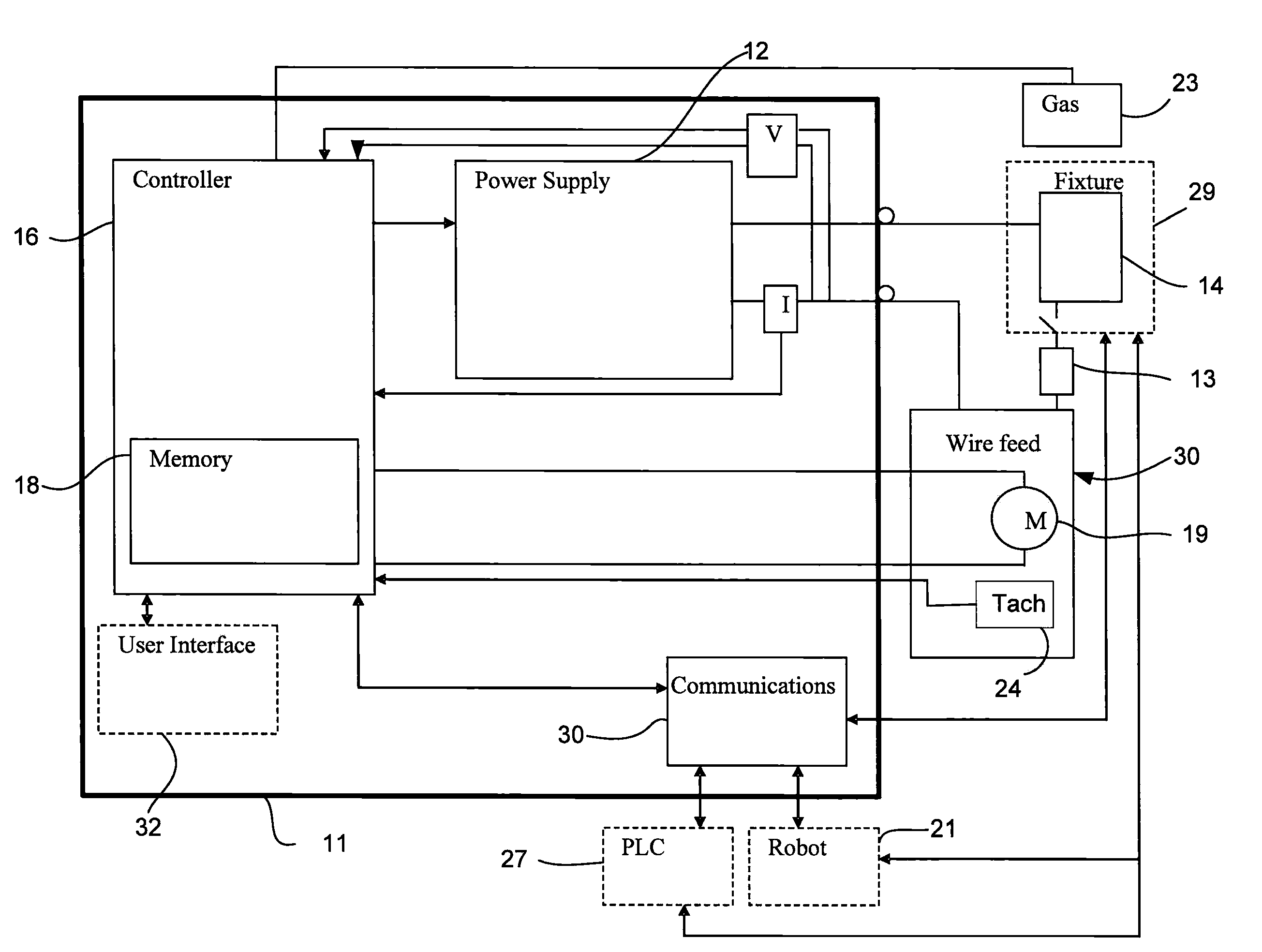
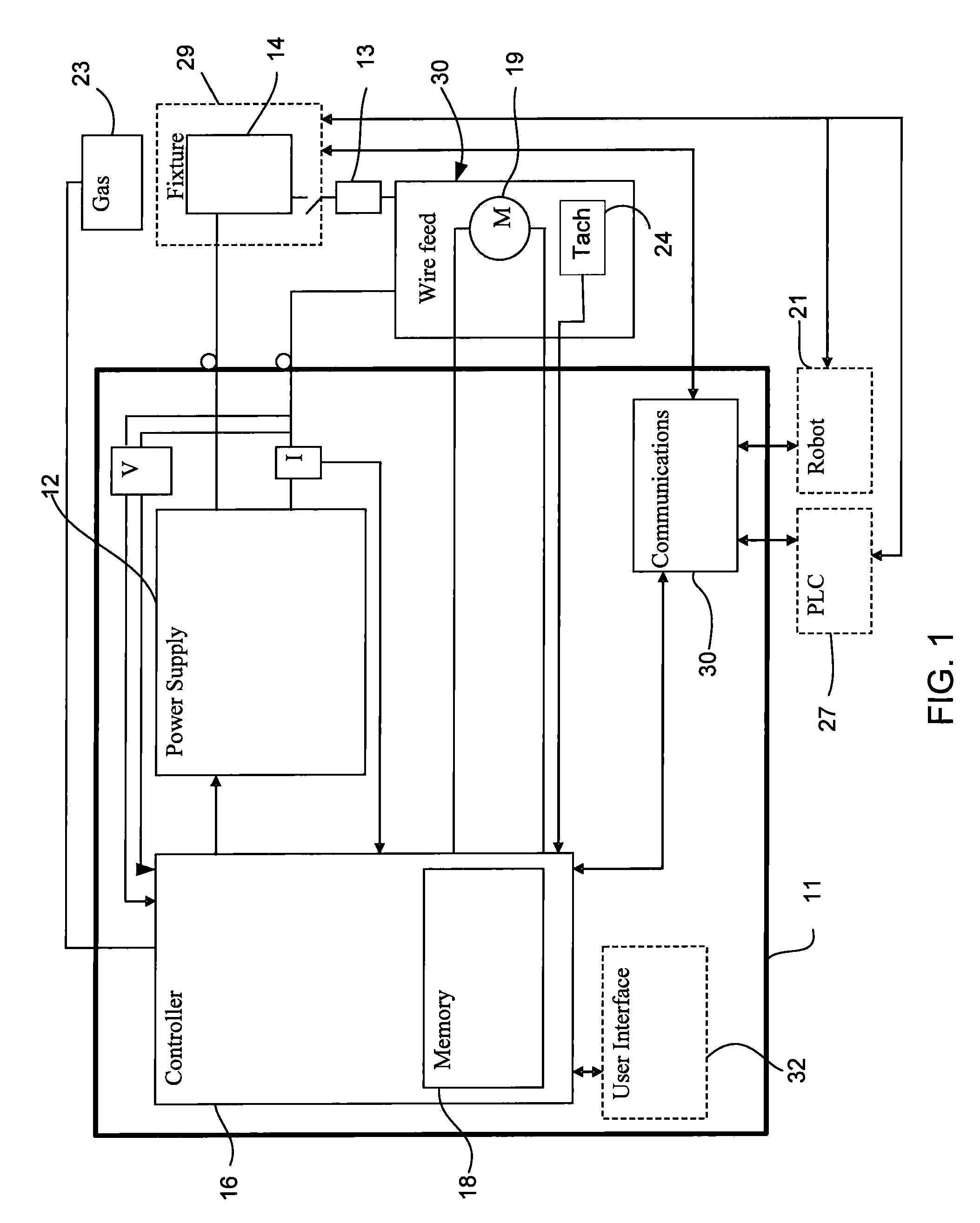
[0032]Referring now to the Figures and more particularly to FIG. 1, an exemplary welding system 10 is shown. The welding system 10 includes a housing 11 containing a power supply 12, a controller 16, and a communications system 30. The controller 16 can include one or more microcontroller, microprocessor, digital signal processor, or other programmable controller, along with an internal or external memory component 18, capable of storing welding programs and procedures specified by the user. Bidirectional communications between the controller 16 and external devices are provided through the communications system 30, preferably through a serial communications link such as DeviceNet, Profibus, RS-232 or other communications systems, or through a network communications device such as an Ethernet connection or other wired or wireless communication devices. The controller 16 may also be connected to a user interface 32, which can be mounted in the housing 11, or provided external to the ...


PUM

PropertyMeasurementUnit
poweraaaaaaaaaa
timeaaaaaaaaaa
inductanceaaaaaaaaaa

Abstract

A welding system including an arc monitoring, training, and control system is disclosed. The welding system includes a power supply, controller, and associated memory. When a weld is performed, the weld command and weld feedback parameters can be stored in the memory, along with associated alarm limit values. During subsequent welds, the input weld commands and actual feedback values can be compared to the established limits, and a fault signal provided to an operator or supervisor when the value exceeds the established limits. The fault signals can be used for training operators, as well as providing monitoring signals, and can be stored with weld data in a database for later analysis. In addition, collected weld data can be used to determine when to clean, repair, or replace consumables, including, for example, contact tips, wire drive liners, and drive rolls, and to monitor usage of wire and gas.

Description

CROSS-REFERENCE TO RELATED APPLICATIONS[0001]This application claims the benefit of U.S. provisional application 61 / 019,972 filed Jan. 9, 2008, which is hereby incorporated by reference in its entirety.FIELD OF THE INVENTION[0002]The present invention is directed to a method and apparatus for monitoring arc data in welding systems, and more specifically to a welding system including an internal arc monitoring system for monitoring weld data, training operators, and communicating resultant weld data to internal databases and external devices.BACKGROUND OF THE INVENTION[0003]As the level of automation has increased in mass production facilities, and the speed of welding operations has increased, it has become increasingly important for management personnel to monitor and control welding parameters and processes to assure consistent and proper joining of materials, and to ensure that completed welds fall within predetermined quality parameters.[0004]To provide a high level of consisten...

Claims


Application Information

Patent Timeline
Patent Type & Authority Applications(United States)
IPC IPC(8): B23K9/10
CPCB23K9/0956G05B19/40937G05B2219/50206G05B2219/37217G05B19/414Y02P90/02B23K9/0953
Inventor DAVIDSON, ROBERT RAIMUNDFLNK, JOSEPH KYLECLEVELAND, PAUL WARREN
Owner ILLINOIS TOOL WORKS INC
Why Eureka
Try Eureka