Method for manufacturing enclosures of a sheet material and an enclosure of a sheet material

Inactive Publication Date: 2009-07-09
ENSTO FINLAND
3 Cites 4 Cited by

AI-Extracted Technical Summary

Problems solved by technology

When using a star blank as the initial blank for an enclosure of a sheet material, the disadvantage is the high probability of a high waste percentage of material, due to the star form.
The area remaining in the corners of the sheet blank is relatively small and thus, difficult to use, ...

Method used

[0035]The edge shape of the orifice can also be folded with the first folding tool 2 by using two or several successive folding steps for providing the shape. In this case, the number of folding tools will decrease (no forming tool 1 will be needed), but the number of folding strokes will increase. The seams of the enclosure can be joined or locked by welding, glue, rivets, or screws. The corners of the enclosure can be welded also at the unopened section 8. According to an advantageous embodiment, the end of the open-cut section 7 at the edge of the sheet blank there is a short unopened isthmus for guiding the folding edge in a desired way and for reducing the ...

Benefits of technology

[0011]It is an object of the invention that once a setting for enclosures of a certain size has been made to the folding machine, it will not be nece...

Abstract

The invention relates to a method for manufacturing an enclosure of a sheet material and to an enclosure of a sheet material, which is manufactured of a sheet blank, of which the sides and the base of the enclosure have been folded, and the seams have been joined together. At least one corner to be folded of the enclosure is cut open from a part of the range in the sheet blank so that the unopened section corresponds to the smallest dimension to be folded in the product series of enclosures.

Application Domain

Rigid containersHollow articles

Technology Topic

EngineeringSheet material

Image

  • Method for manufacturing enclosures of a sheet material and an enclosure of a sheet material
  • Method for manufacturing enclosures of a sheet material and an enclosure of a sheet material
  • Method for manufacturing enclosures of a sheet material and an enclosure of a sheet material

Examples

  • Experimental program(1)

Example

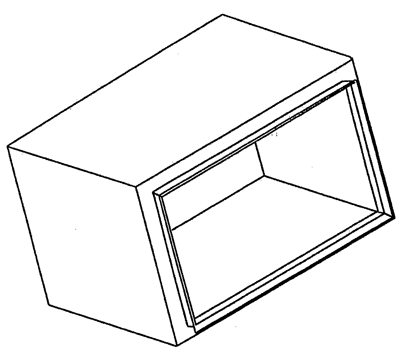
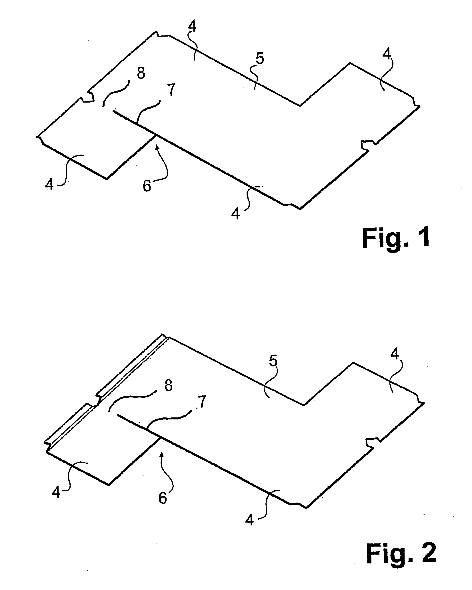
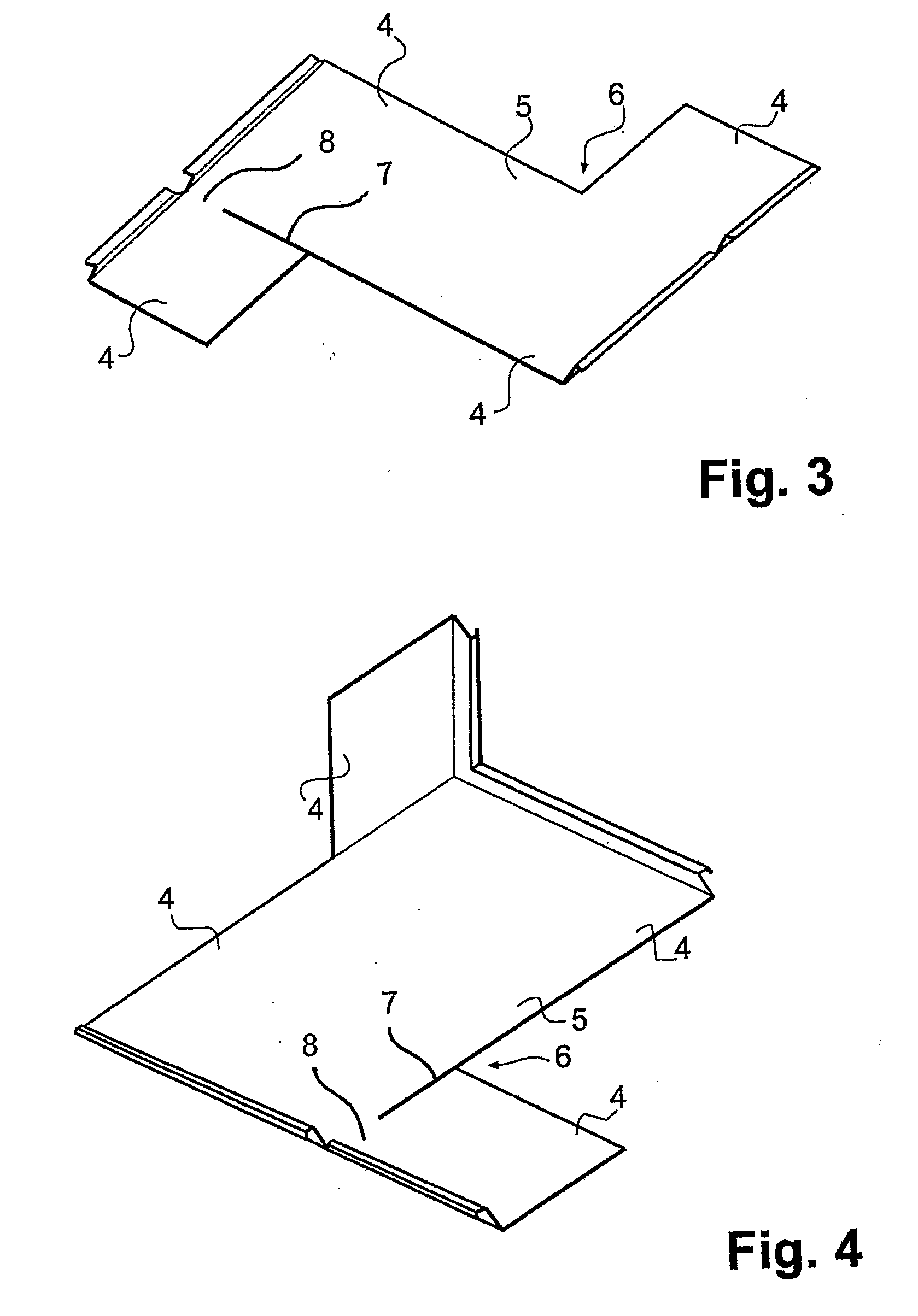
[0033]An enclosure will be manufactured of a sheet blank so that the sides 4 and the base 5 of the enclosure will be folded and the seams will be fastened, the corner 6 to be folded of one enclosure being cut open 7 for a part of the range in the sheet blank. The manufacturing steps will next be explained in more detail by means of the enclosed figures.
[0034]The sheet blank is cut to the desired shape, in this example to the S-shape. After this, the product blanks will be taken to the folding machine. The folding machine has a blade setting according to the FIG. 13 using three different folding tools 1, 2 and 3 made to it. In this example, a separate forming tool 1 is used for folding the orifice; long folds will be made with the first folding tool 2, and the folding of the open-cut corner will be made with the second folding tool 3. When using these folding tools, the folding sequence is the following: Folding the two first edges of the orifice with the forming tool 1, FIG. 2, after which the first corner between the two sides will be folded with the first folding tool 2, FIG. 3. After this, the two latter edges of the orifice will be folded with the forming tool 1, FIG. 4, and the first folding tool 2 will then be used for folding the two corners between the bottom and the side, FIGS. 5 and 6. Then, the open-cut last corner between the sides will be folded with the second folding tool 3 so that the enclosure will be closed. After this, the enclosure will be ready for welding. Thus, the basic principle in this example is the use of three fixed folding tools so that one of these, the forming tool 1, will be used for folding the shape of the orifice. The width of the folding tools can be chosen according to the maximum dimensions of the product series, because the folding tool 1,2 can always “come out of the enclosure”. The first folding tool 2 will be used for folding all such corners, in which the folding tool will extend “out of the enclosure” from at least one end so that the width of the folding tool can still be chosen according to the maximum dimension. The second folding tool 3 will be used for folding the corners in a case, in which the enclosure is already closed so that the blade cannot come freely “out” of the enclosure. The width of the folding tool can be chosen according to the smallest dimension to be folded in the product series, and the folding line of the sheet blank will be cut open for the section, which exceeds the width of the second folding tool 3 as the size of the enclosure increases. In this case, the unopened section 8 of the corner 6 is uniform, and its length is at most of the size of the shortest side or of the shortest side to be folded last in a product series of different-sized enclosures of a sheet material. When, in practice, the enclosures always have a light aperture, the shape will eventually become so closed that it is preferable to fold at least one corner by means of the method of the present invention.
[0035]The edge shape of the orifice can also be folded with the first folding tool 2 by using two or several successive folding steps for providing the shape. In this case, the number of folding tools will decrease (no forming tool 1 will be needed), but the number of folding strokes will increase. The seams of the enclosure can be joined or locked by welding, glue, rivets, or screws. The corners of the enclosure can be welded also at the unopened section 8. According to an advantageous embodiment, the end of the open-cut section 7 at the edge of the sheet blank there is a short unopened isthmus for guiding the folding edge in a desired way and for reducing the deformations of the open-cut to be welded or joined otherwise.
[0036]As in this case, the starting point is at least one open-cut corner 6, and the length if the fixed section of the corner has been chosen according to the enclosure with the smallest dimension in the product series, it is no more of significance, from which end the corner is open or if it is open from both ends, or if one corner or all four corners are cut open, or of the fixed section in the corner is uniform or not. Of the sheet blank models, S, T and L are the most interesting ones, because in these, the material waste is most often the smallest. At the end points, the open-cut section 7 can be different from the other parts, e.g. V-shaped so that the location of the sheet edges after the folding in relation to each other can be made advantageous with regard to joining, such as welding. The sheet blank or the share 7 of the open-cut corner to be folded in the blank can advantageously be cut, for example, by laser or water cutting.
[0037]A corner partly cut open, with narrow isthmuses, may be needed either for totally eliminating the internal tool or for optimising the folding shape, for example, in relation to welding or appearance when using the internal tool. Instead of a straight open cut, for example, a V-shaped form can be used for optimising the folding shape at the end points so that the edges of the sheet can be positioned into a more advantageous position in relation to each other, for example, for welding. Thus, there may be open-cut sections 7 in the corner 6 to be folded last on both sides of the unopened section 8.

PUM

PropertyMeasurementUnit
Length
Size

Description & Claims & Application Information

We can also present the details of the Description, Claims and Application information to help users get a comprehensive understanding of the technical details of the patent, such as background art, summary of invention, brief description of drawings, description of embodiments, and other original content. On the other hand, users can also determine the specific scope of protection of the technology through the list of claims; as well as understand the changes in the life cycle of the technology with the presentation of the patent timeline. Login to view more.
Why Eureka
Try Eureka