Current differential relay device, signal processing method thereof and power transmission line protection system

a relay device and current differential technology, applied in circuit arrangements, emergency protective circuit arrangements, electrical equipment, etc., can solve the problems of power transmission line protection function of current differential relay devices that stop, and the operating ratio of current differential relay devices also drops, so as to achieve high reliability and high operating ratio

Active Publication Date: 2009-07-09
KK TOSHIBA
View PDF4 Cites 10 Cited by
  • Summary
  • Abstract
  • Description
  • Claims
  • Application Information

AI Technical Summary

Benefits of technology

[0041]The present invention is able to provide a highly reliable current differential relay device of a high operating ratio which is capable of continuing the power transmission line protection function without stopping same while maintaining the sampling synchronization between a plurality of terminals even when one of the duplexed transmission paths has a transmission defect, as well as to provide a signal processing method for the current differential relay device and a power transmission line protection system.

Problems solved by technology

However, when a transmission defect arises in the regular use transmission path, the power transmission line protection function of the current differential relay device stops during the confirmation time up until the reception changeover into the standby transmission path is completed.
Furthermore, in cases where an intermittent transmission defect arises, transmission path reception changeover is not carried out and repeat of the stoppage and operation of the power transmission line protection function in the current differential relay device occur sometimes. In this case, the operating ratio of the current differential relay device also drops.

Method used


Image

  • Current differential relay device, signal processing method thereof and power transmission line protection system
  • Current differential relay device, signal processing method thereof and power transmission line protection system
  • Current differential relay device, signal processing method thereof and power transmission line protection system

Examples


first embodiment

[Configuration]

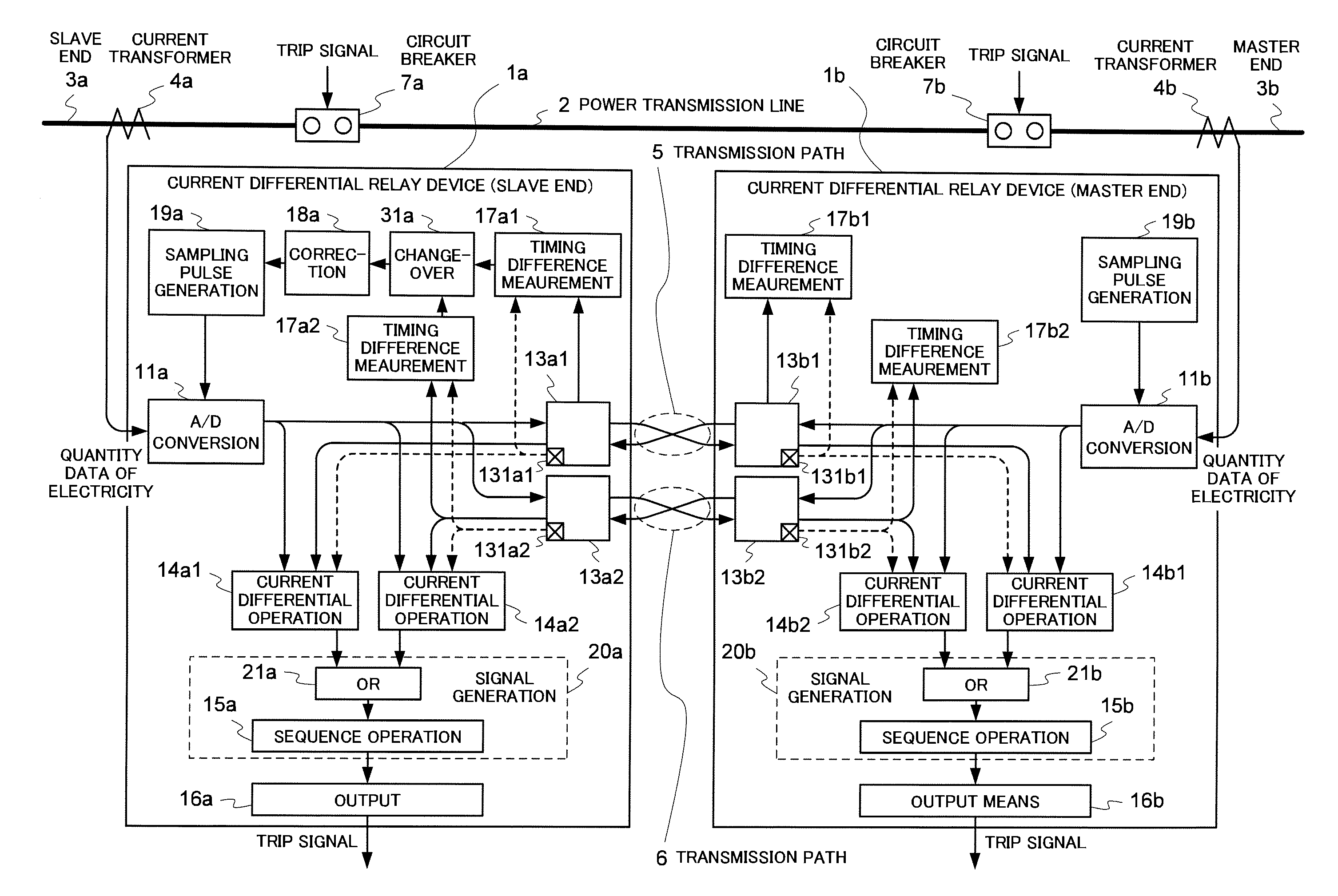
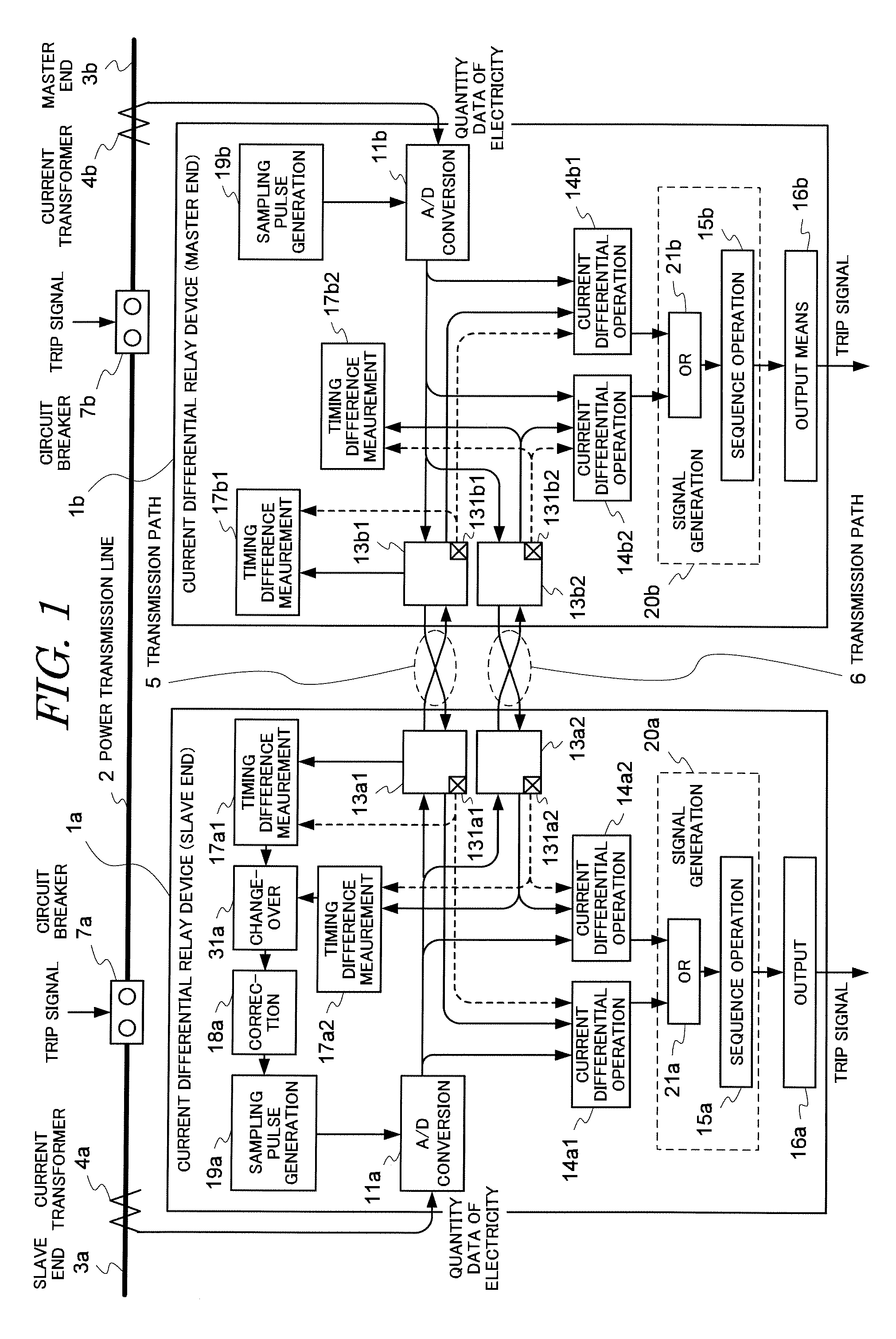
[0072]FIG. 1 is a configuration diagram of the power transmission line protection system according to the first embodiment to which the present invention is applied. The basic configuration of the power transmission line protection system shown in FIG. 1 is the same as that of the conventional system shown in FIG. 4. In other words, the two current differential relay devices 1 (1a, 1b) are installed in the respective terminals 3 (slave end 3a and master end 3b) of the two-terminal power transmission line 2 and connected to each other via two transmission paths 5 and 6 so as to carry out a current differential operation by transmitting and receiving quantity data of electricity of their respective terminals to each other.

[0073]In the current differential relay device 1 of this embodiment, firstly, two transmission means 13*1 and 13*2 (*=a, b), two current differential operation means 14*1 and 14*2 (*=a, b), and two timing difference measurement means 17*1 and 17*2 (*=a...

second embodiment

[Configuration]

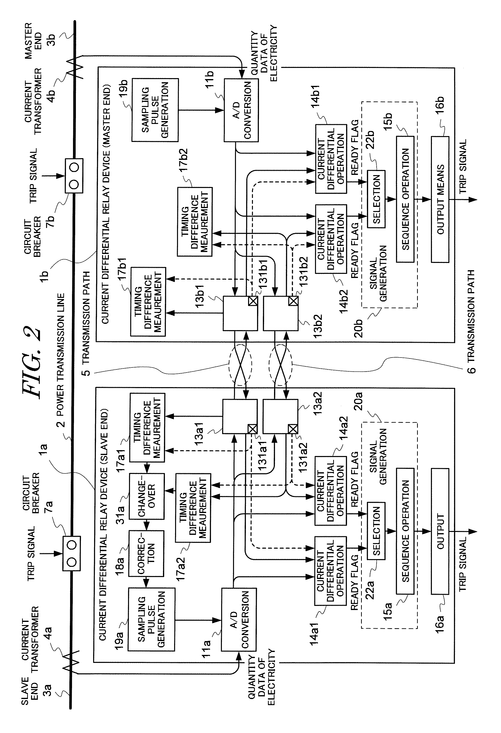
[0085]FIG. 2 is a configuration diagram of the power transmission line protection system according to the second embodiment to which the present invention is applied. The basic configuration of the power transmission line protection system shown in FIG. 2 is the same as that of the first embodiment shown in FIG. 1 but differs from that of the first embodiment with respect to the following points.

[0086]That is, in the current differential relay device 1 of the second embodiment, a ready flag which indicates whether the current state is a locked state or a ready state is outputted by the current differential operation means 14*1 and 14*2 in addition to the current differential operation result. In addition, the signal generation means 20 is provided with selection means 22 for selecting the current differential operation result to be used in accordance with the ready flag instead of the logical disjunction means 21. The remaining configuration is the same as the configu...

third embodiment

[Configuration]

[0092]FIG. 3 is a configuration diagram of a power transmission line protection system according to the third embodiment to which the present invention is applied. The basic configuration of the power transmission line protection system shown in FIG. 2 is the same as that of the first embodiment shown in FIG. 1 but differs from that of the first embodiment with respect to the following points.

[0093]That is, in the current differential relay device 1 of the third embodiment, a logical conjunction means (AND) 23, which takes the logical conjunction of the two-series current differential operation results, is provided in the signal generation means 20 in place of the logical disjunction means 21. The remaining configuration is the same as the configuration of the first embodiment.

[Action]

[0094]In the power transmission line protection system according to the third embodiment which has a configuration such as that described above, the action, which differs from that of th...


PUM


Abstract

Two current differential relay devices 1 are installed at each terminal 3 of a two-terminal power transmission line 2, and connected to each other via two transmission paths 5 and 6, and perform current differential operations by transmitting and receiving the quantity data of electricity to each other. In the current differential relay device 1, two transmission means 14 normally each perform communications with the current differential relay device 1 of the other end of the power transmission line in parallel through the two transmission paths 5 and 6. Two current differential operation means 14 are connected to the two transmission means 14 respectively and perform independently two-series of current differential operations independently for each series associated with each of the transmission paths 5 and 6. The signal generation means 20 obtains the logical disjunction of the two-series of current differential operation results by means of the logical disjunction means 21 and uses the logical disjunction to generate a trip signal by means of the sequence operation means 15. The present invention provides a highly reliable current differential relay device of a high operating ratio which is capable of continuing the power transmission line protection function without any discontinuation even when one of the duplexed transmission paths has a transmission defect, as well as providing a signal processing method for the current differential relay device and a power transmission line protection system.

Description

TECHNICAL FIELD[0001]The present invention relates to a current differential relay device which protects a power transmission line of an electric power system and, more particularly, to a current differential relay device which performs data communications via two transmission paths.BACKGROUND OF THE INVENTION[0002]Conventionally, systems of every kind which employ a current differential relay device for the purpose of protecting a power transmission line of an electric power system have been proposed. FIG. 4 is a configuration diagram of an example of such a conventional power transmission line protection system and, in particular, of a transmission path duplex system in which transmission paths are duplexed.[0003]In the power transmission line protection system shown in FIG. 4, two current differential relay devices 1 (1a and 1b) are installed at the respective terminals 3 (slave end 3a and master end 3b) of a two-terminal power transmission line 2. The two current differential re...

Claims


Application Information

Patent Timeline
Patent Type & Authority Applications(United States)
IPC IPC(8): H02H3/28
CPCH02H3/28H02H3/30
Inventor SAGA, MASAMICHISHUTO, ITSUOMIZUNOUE, MITSUAKI
Owner KK TOSHIBA
Why Eureka
Try Eureka