Vibration transducer

a technology of vibration transducer and film, which is applied in the direction of electrical transducer, electrical transducer, electrical apparatus, etc., can solve the problems of reducing the sensitivity of the condenser microphone, affecting the environmental resistance of the condenser, and affecting the energy of the sound wave transmitted through the film, so as to achieve the effect of improving the environmental resistan

Inactive Publication Date: 2009-07-09
YAMAHA CORP
View PDF7 Cites 77 Cited by
  • Summary
  • Abstract
  • Description
  • Claims
  • Application Information

AI Technical Summary

Benefits of technology

[0010]It is an object of the present invention to provide a miniature vibration transducer such as a condenser microphone, which is improved in environmental resistance without causing a sensitivity reduction.

Problems solved by technology

When the through-hole of the package is closed with the film composed of polytetrafluoroethylene or sintered metal as disclosed in Patent Document 2, the energy of sound waves transmitted through the film may be greatly damped, thus reducing the sensitivity of the condenser microphone.

Method used


Image

  • Vibration transducer
  • Vibration transducer
  • Vibration transducer

Examples


first embodiment

1. First Embodiment

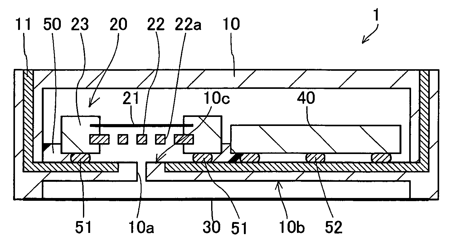
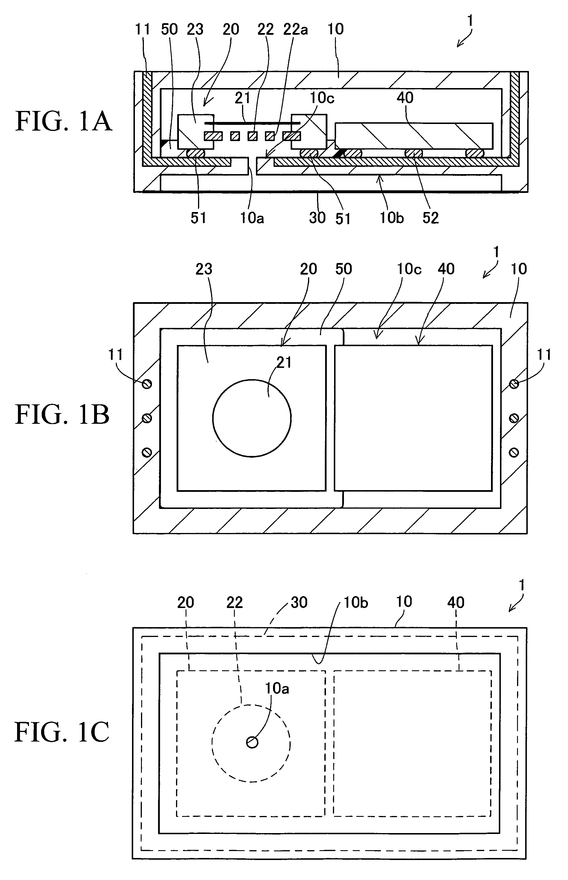
[0042]FIG. 1A is a longitudinal sectional view of a vibration transducer, i.e. a condenser microphone 1 in accordance with a first embodiment of the present invention. FIG. 1B is a horizontal sectional view of the condenser microphone 1. FIG. 1C is a backside view of the condenser microphone 1, from which a barrier diaphragm 30 is removed.

[0043]The condenser microphone 1 of the first embodiment is a miniature condenser microphone serving as an MEMS sensor, which is installed in a portable electronic device such as a cellular phone. Specifically, the condenser microphone 1 is constituted of a microphone die 20 serving as a vibration conversion die, an amplifier die 40, and a housing 10 for storing them as well as the barrier diaphragm 30 for covering a through-hole 10a of the housing 10.

[0044]The housing 10 has a box-like shape forming a space for storing the microphone die 20 and the amplifier die 40. Housing 10 is composed of an airtight material, which is select...

second embodiment

2. Second Embodiment

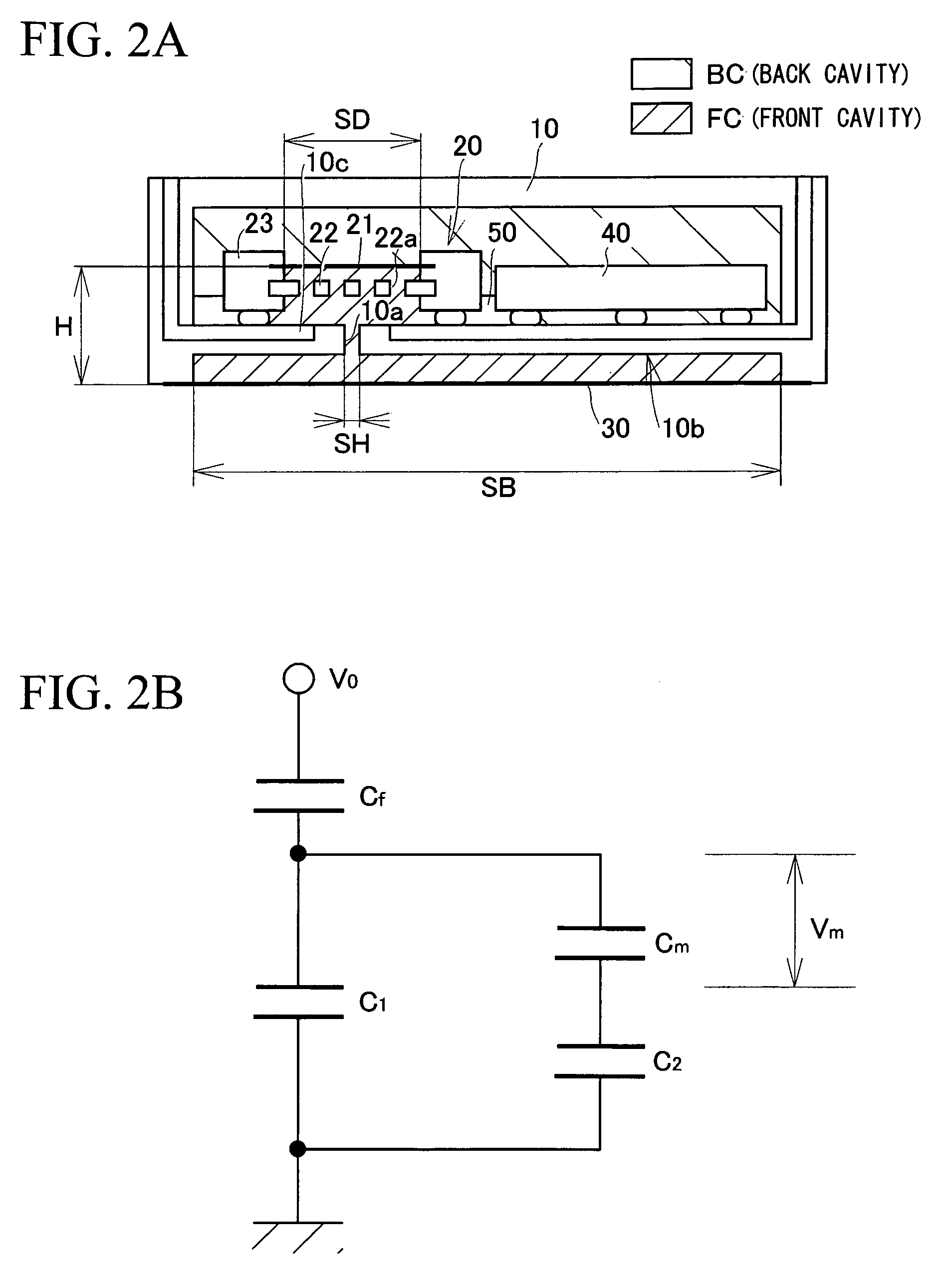
[0080]FIG. 3 is a longitudinal sectional view of a condenser microphone 2, which is a vibration transducer in accordance with a second embodiment of the present invention. Herein, the electrode diaphragm 21 is positioned below the electrode plate 22 and close to the barrier diaphragm 30.

third embodiment

3. Third Embodiment

[0081]FIG. 4A is a longitudinal sectional view of a condenser microphone 3, which is a vibration transducer in accordance with a third embodiment of the present invention. FIG. 4B is a horizontal sectional view of the condenser microphone 3 from which a barrier diaphragm 31 is removed from the backside.

[0082]Generally speaking, it is preferable that the gap between the barrier diaphragm and the exterior surface of the housing be minimized in conformity with vibration of the barrier diaphragm. In the third embodiment, the diaphragm 31 is positioned to tightly close a conical recess (or a tapered recess) of a housing 12 (having the through-hole 10a). The barrier diaphragm 31 has an axially symmetrical vibration mode in a lower frequency range lower than the resonance frequency thereof. That is, the amplitude of the barrier diaphragm 31 becomes small in a direction from a vibration axis BA (substantially corresponding to the center of the barrier diaphragm 31) to a v...


PUM


Abstract

A vibration transducer (e.g. a condenser microphone) having a high sensitivity is constituted of a housing composed of an airtight material having a through-hole, a vibration conversion die (e.g. a microphone die) which is attached to the interior surface of the housing at the prescribed position embracing the through-hole in plan view, and a barrier diaphragm composed of an airtight material whose external periphery is attached to the exterior surface of the housing in an airtight manner oppositely to the prescribed position. The barrier diaphragm has a vibration area which is larger than the sectional area of the through-hole. A space allowing the barrier diaphragm to vibrate is formed between the barrier diaphragm and the exterior surface of the housing, wherein the distance between the barrier diaphragm and the exterior surface of the housing can be gradually reduced from the vibration axis to the external periphery.

Description

BACKGROUND OF THE INVENTION[0001]1. Field of the Invention[0002]The present invention relates to vibration transducers and in particular to miniature vibration transducers such as condenser microphones serving as MEMS (Micro-Electro-Mechanical System) sensors.[0003]The present application claims priority on Japanese Patent Application No. 2007-213657, the content of which is incorporated herein by reference.[0004]2. Description of the Related Art[0005]Conventionally, various types of miniature condenser microphones, which are manufactured by way of semiconductor device manufacturing processes, have been known and disclosed in various documents such as Patent Document 1 and Patent Document 2.[0006]Patent Document 1: Japanese Unexamined Patent Application Publication No. 2001-78297[0007]Patent Document 2: Japanese Unexamined Patent Application Publication No. 2004-537182[0008]Through-holes for propagating sound waves are formed in the housing of miniature condenser microphones. In the...

Claims


Application Information

Patent Timeline
Patent Type & Authority Applications(United States)
IPC IPC(8): H04R19/04
CPCH04R19/04
Inventor SUZUKI, YUKITOSHISUZUKI, TOSHIHISAMUROI, KUNIMASANAGATA, TATSUYA
Owner YAMAHA CORP
Why Eureka
Try Eureka