Dispersion compensation method and fiber transmission system

a fiber transmission system and dispersion compensation technology, applied in the field of fiber communication, can solve the problems of large volume, large volume, and inability to ignore the impact of dispersion on system performance, and achieve the effect of suppressing the non-linear effect of dispersion compensation

Inactive Publication Date: 2009-07-09
HUAWEI TECH CO LTD
View PDF15 Cites 36 Cited by
  • Summary
  • Abstract
  • Description
  • Claims
  • Application Information

AI Technical Summary

Benefits of technology

[0011]Embodiments of the present disclosure provide a dispersion compensation method and a fiber transmission system to overcome the weaknesses of

Problems solved by technology

Dispersion generates inter-symbol interferences between data pulses in the optical transmission.
The impact of dispersion on the system performance cannot be ignored.
This dispersion compensation mode is easy to use, but has the following unavoidable weaknesses: large volume, signal delay, need of an amplifier for additional loss compensation, and high cost.
This compensation mode cannot provide flexible dispersion compensation.
Though the DCF mode has practical utility in a point-to-point optical transmission system, it is difficult to meet application requirements in a complicated network with wavelength add/drop, especially in a flexible network that may be dynamically rebuilt.
The electrical domain compensation mode, however, has limitations.
The

Method used


Image

  • Dispersion compensation method and fiber transmission system
  • Dispersion compensation method and fiber transmission system
  • Dispersion compensation method and fiber transmission system

Examples


Embodiment Construction

[0011]Embodiments of the present disclosure provide a dispersion compensation method and a fiber transmission system to overcome the weaknesses of the long-distance dispersion compensation without online DCF and to suppress the non-linear effect of the dispersion compensation in the prior art.

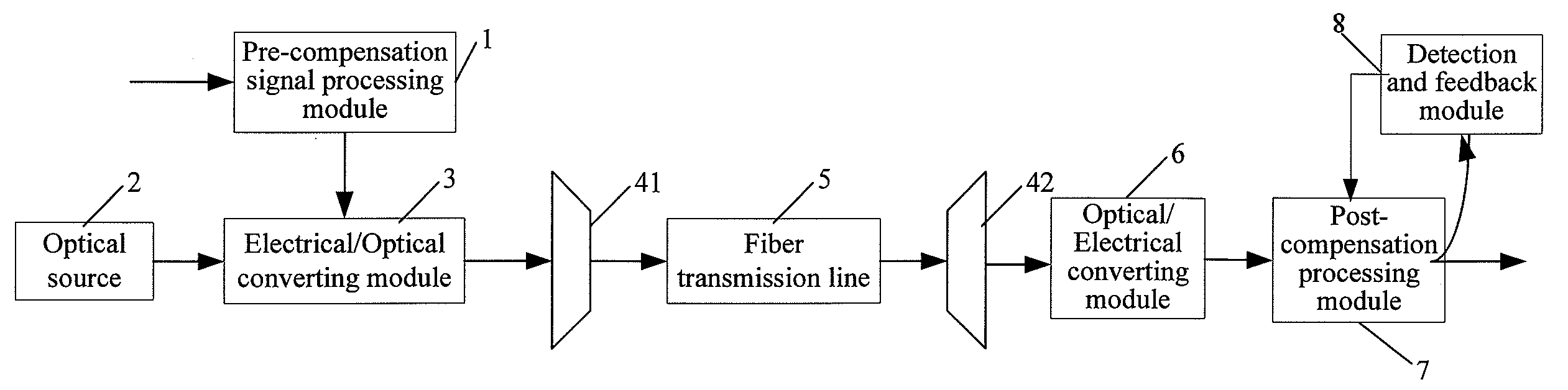
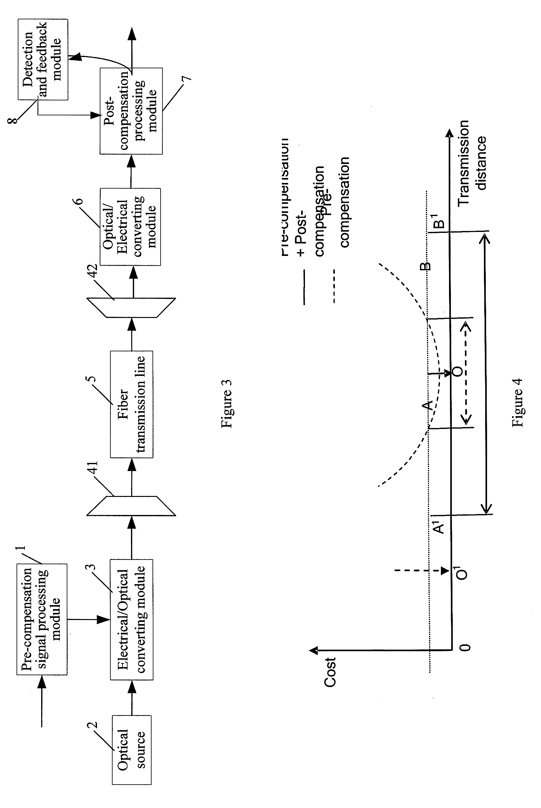
[0012]A dispersion compensation method includes: performing, by a transmitting end, electrical pre-compensation processing on a transmit signal to obtain a distorted electrical signal, and converting an optical carrier signal into a distorted optical signal through modulation according to the distorted electrical signal; and after recovering the distorted optical signal to a recovered optical signal through a transmission line, sending the signal to a receiving end; upon receipt of the recovered optical signal, the receiving end, performs post-compensation processing after converting the recovered optical signal into a pre-compensation electrical signal, or performs post-compensation processing...


PUM


Abstract

A dispersion compensation method and a fiber transmission system are disclosed, pertaining to the field of fiber communications. The dispersion compensation method includes: after performing electrical pre-compensation processing on a digital transmit signal, the transmitting end controls the electrical/optical converting module to output a distorted optical signal; after receiving the optical signal, the receiving end performs post-compensation processing after converting the optical signal into an electrical signal, or converts the optical signal into an electrical signal after performing post-compensation processing on the optical signal. The fiber transmission system includes: a pre-compensation signal processing module, an optical source, an electrical/optical converting module, a fiber transmission line, an optical/electrical converting module, and a post-compensation processing module. With the technical solution of the present disclosure, the non-linear effect may be suppressed, and a flexible dispersion compensation solution may be provided for a dynamically configurable network.

Description

CROSS-REFERENCE TO RELATED APPLICATIONS[0001]This application is a continuation application of PCT / CN2007 / 002587, filed on Aug. 28, 2007, which claims the priority benefit of Chinese Patent Application No. 200610167786.1, filed on Dec. 21, 2006. The contents of the above identified applications are incorporated herein by reference in their entirety.FIELD OF THE DISCLOSURE [0002]The present disclosure relates to fiber communications, and in particular, to a dispersion compensation method and a fiber transmission system.BACKGROUND OF THE DISCLOSURE [0003]Dispersion means that the waveform of a transmit signal in a fiber is distorted due to different frequency components or different transmission rates of signal components in different modes. Dispersion generates inter-symbol interferences between data pulses in the optical transmission. The impact of dispersion on the system performance cannot be ignored. An optical transmission system with the transmission rate of more than 10 Gbit / s...

Claims


Application Information

Patent Timeline
IPC IPC(8): H04B10/12H04B10/00H04B10/04H04B10/06H04B10/2513
CPCH04B10/25137H04B10/25133
Inventor LIU, YUEFU, WEITAO, ZHIHUI
Owner HUAWEI TECH CO LTD
Why Eureka
Try Eureka