Retaining formation

Active Publication Date: 2009-07-09
MERITOR HEAVY VEHICLE BRAKING SYST (UK) LTD
View PDF12 Cites 6 Cited by
  • Summary
  • Abstract
  • Description
  • Claims
  • Application Information

AI Technical Summary

Benefits of technology

[0020]In this manner, the potential problems caused by

Problems solved by technology

This solution is problematic, as in certain situations, the push rod can return before the lever.
However, the brake mechanism may be slow to respond due to the low temperature causing increased viscosity in the lubricant.
The push rod and the lever can become disengaged and misaligned such that on a subsequent actuation stroke, the push rod either contacts the lever at the incorrect position, or does not contact it

Method used


Image

  • Retaining formation
  • Retaining formation
  • Retaining formation

Examples


Example

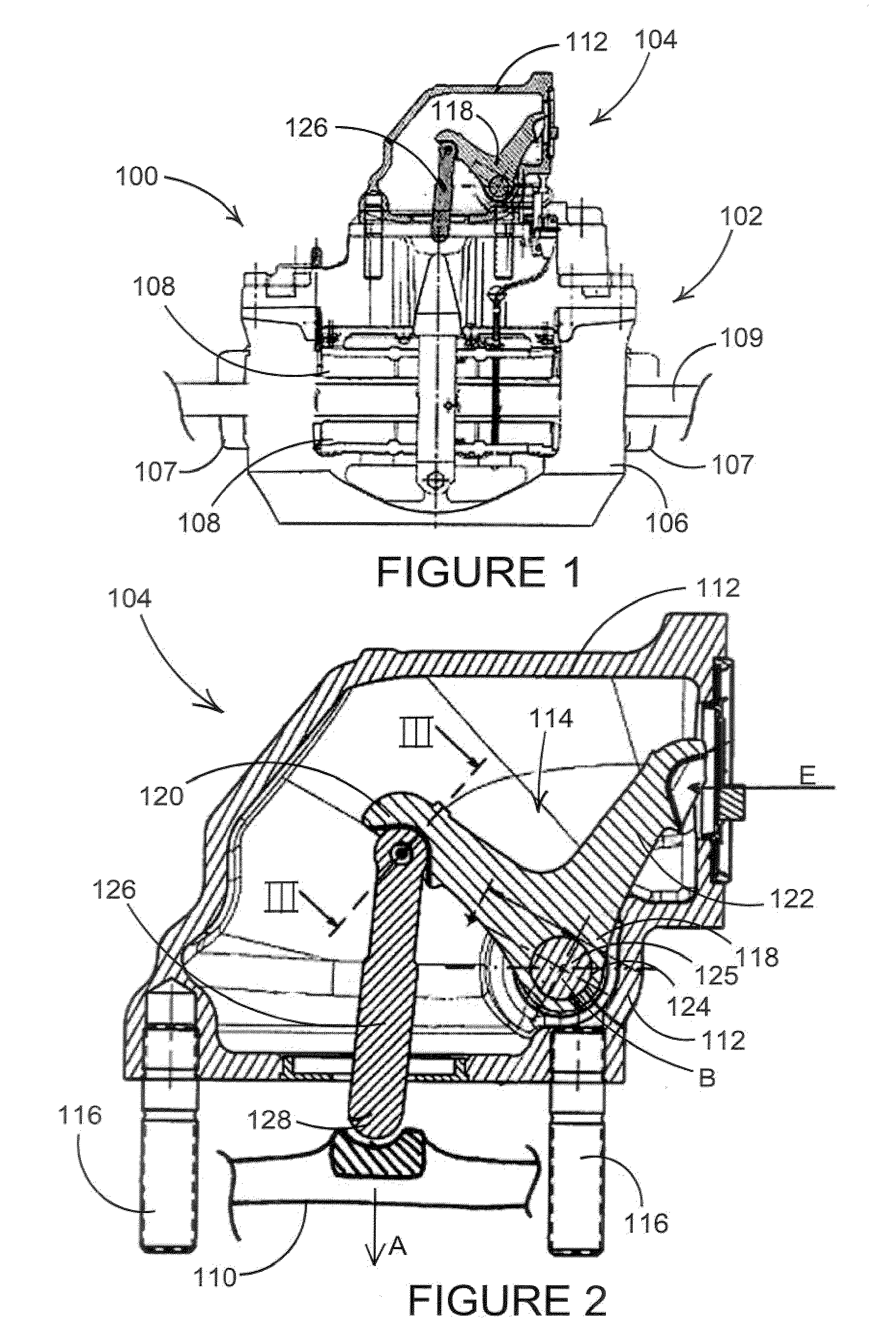
[0037]A brake assembly 100 is shown in FIG. 1. The brake assembly 100 includes a brake subassembly 102 and an adaptor box subassembly 104. The brake subassembly 102 includes a brake caliper 106 slidably mounted with respect to a brake carrier 107 and a pair of opposed brake pads 108 for actuation and engagement with a brake disc or rotor 109 to provide a braking force for retarding rotation of a wheel (not shown) of a vehicle (not shown). The basic layout and purpose of an adaptor box is shown in our earlier application EP1348882.

[0038]The brake pads 108 are pushed into engagement with the brake disc or rotor 109 via an op-shaft 110 of the brake subassembly 102 (see FIG. 2) via an actuation force in a direction A. The op-shaft 110 converts a relatively high displacement, low force input from an air actuator into a low displacement, high force output to the brake pads 108 in a known manner.

[0039]The adaptor box subassembly 104 includes an adaptor box housing 112, an adaptor subassemb...


PUM


Abstract

A retaining formation defined on a brake lever of an air disc brake includes a push fit/snap fit connection for releasably securing a push rod to a brake lever. The retaining formation can include a pinned connection and a ball and socket joint, and a main axis of the pinned connection is coincident with a center of rotation of the ball and socket joint. The retaining formation can include a concave formation on one of the push rod and the brake lever and a corresponding convex formation on the other of the push rod and the brake lever. The concave formation at least partially surrounds the convex formation to prevent axial separation of the push rod and the brake lever. A method of assembling a brake subassembly includes the steps of assembling a push rod and a brake lever including a retaining formation such that at least a portion of the retaining formation deforms during assembly and resiles when the push rod is assembled to the brake lever to provide a snap fit connection therebetween. Another method of manufacturing a retaining formation includes the steps of providing one of a push rod and a brake lever with a concave formation, providing the other of the push rod and the brake lever with a convex formation able to receive the concave formation, assembling the concave formation and the convex formation, mechanically working the one of the push rod and the brake lever with the concave formation such that the concave formation at least partially surrounds the convex formation to prevent axial separation of the push rod and the brake lever.

Description

REFERENCE TO RELATED APPLICATION[0001]This application claims priority to United Kingdom Patent Application No. 0725225.7 filed Dec. 24, 2007.BACKGROUND OF THE INVENTION[0002]The present invention relates generally to a retaining formation for the connection of components in a brake. Specifically, the present invention relates to a retaining clip for the connection of a push rod in an actuator to a lever of an air disc brake.[0003]It is known in brake applications to operate levers such as op-shafts and adaptors with push rods. The push rods act in compression when an actuating force is applied (e.g., by the activation of the brake) and transmit compressive forces in an actuation stroke, for example, between: an actuator and an op-shaft for actuation of a brake, an actuator and an adaptor lever for rotation of the adaptor lever, and an adaptor lever and an op-shaft for actuation of a brake.[0004]The push rod then returns via a return stroke as air pressure is released and a return s...

Claims


Application Information

Patent Timeline
IPC IPC(8): F16C11/06F16D65/18F16D65/28
CPCF16C11/0623F16D2121/14Y10T403/32861F16D2125/70Y10T403/32803F16D2125/32
Inventor ROBERTS, PAULNIEHORSTER, KEITHTAYLOR, MARTIN P.ANAND, V.S. ARULGARGESHWARI S, NAGARAJAMIRJI, PRADEEP D.HOLL, HERR FRANZ HELMUT
Owner MERITOR HEAVY VEHICLE BRAKING SYST (UK) LTD
Why Eureka
Try Eureka