Multistage Turbocompressor

a turbocompressor and multi-stage technology, applied in the direction of machines/engines, stators, liquid fuel engines, etc., can solve the problems of fitting points “gumming”, disassembly of the turbocompressor being only possible with great difficulty, and perhaps no longer possible at all, and achieves high oil pressure

Inactive Publication Date: 2009-07-09
SIEMENS AG
View PDF5 Cites 1 Cited by
  • Summary
  • Abstract
  • Description
  • Claims
  • Application Information

AI Technical Summary

Benefits of technology

[0008]Two sealing elements, which are spaced apart from each other, are provided between the outer wall of the tubular housing and the inner wall of the opening in which the compressor unit is accommodated. These sealing elements, which are spaced apart from each other, together with the outer wall of the tubular housing and the inner wall of the opening in which the compressor unit is accommodated, form an annular space. A fluid feed line, to which fluid, especially oil, can be fed from outside, extends into the space which is thus formed in order to fill the annular space with oil and especially to pressurize the space with high oil pressure. As a result of the high oil pressure which can be thus established in the annular space, gums which are formed as result of compression of contaminated or corrosive gases and which are found between the housing outer wall of the compressor unit and the inner wall of the opening, can be removed by lubricating and expanding, wherein the gums otherwise seriously hamper a withdrawal or forcing out of the compressor unit from the opening which is formed in the form of a close fit, or perhaps make it impossible.
[0009]From an overall viewpoint, radial and / or axial forces can be created by means of the space which is thus formed and which can be pressurized with oil pressure. Gumming-up of the compressor unit in the opening of the compressor unit, which is a result of the compression of contaminated or corrosive gases, can be removed without any problem by means of these forces. A disassembly of the compressor, which for example is to be undertaken for maintenance operations and during which the compressor unit is especially to be released from its opening, can then be undertaken without any problem after loosening of the gum.

Problems solved by technology

A centering which is carried out in sufficiently close fits, however, results in the fitting points “gumming-up” when compressing contaminated or corrosive gases.
This “gumming-up” of the fitting points results in a disassembly of the turbocompressor being possible only with great difficulty and perhaps no longer possible at all.

Method used


Image

  • Multistage Turbocompressor
  • Multistage Turbocompressor
  • Multistage Turbocompressor

Examples


Embodiment Construction

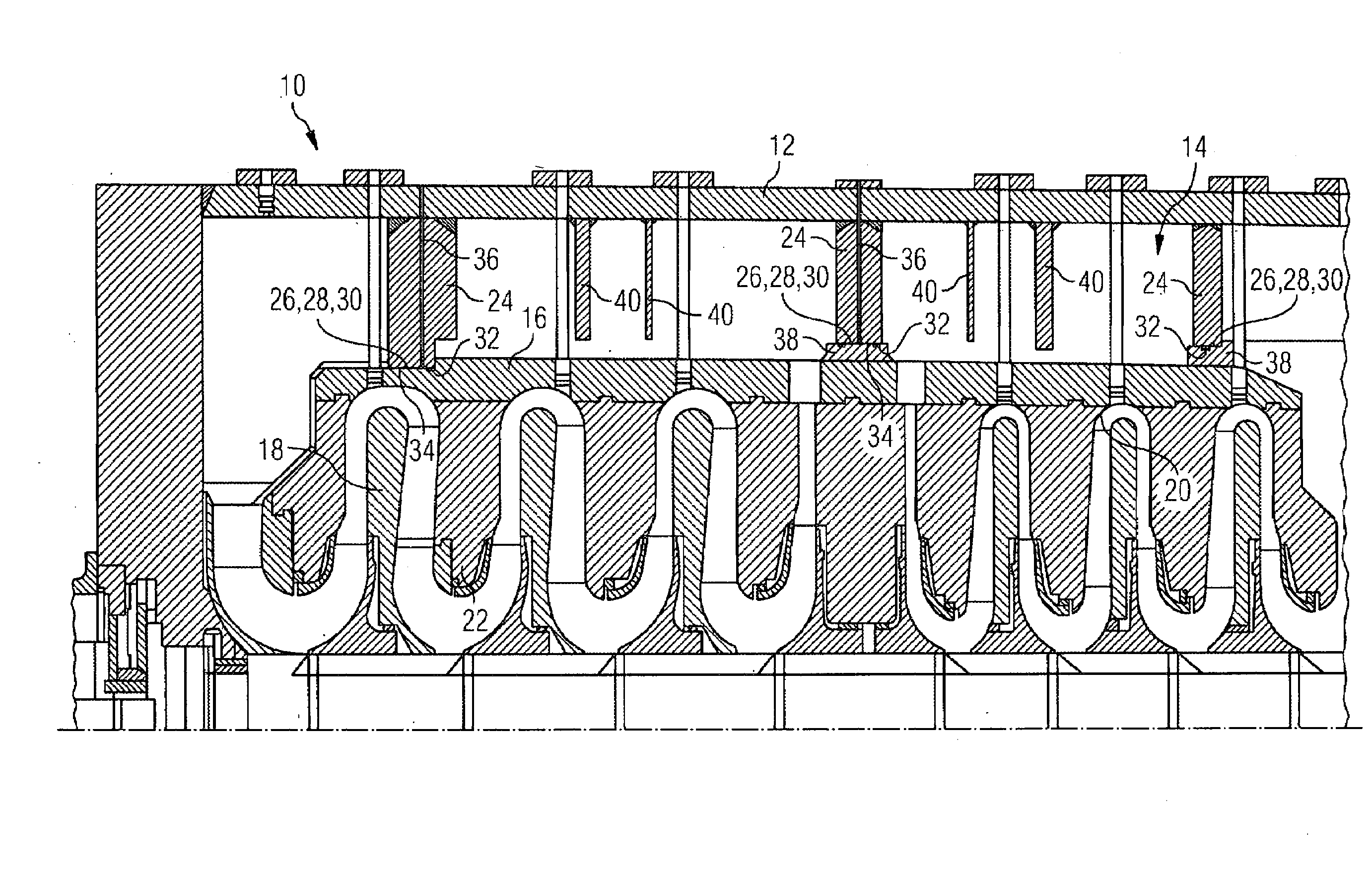
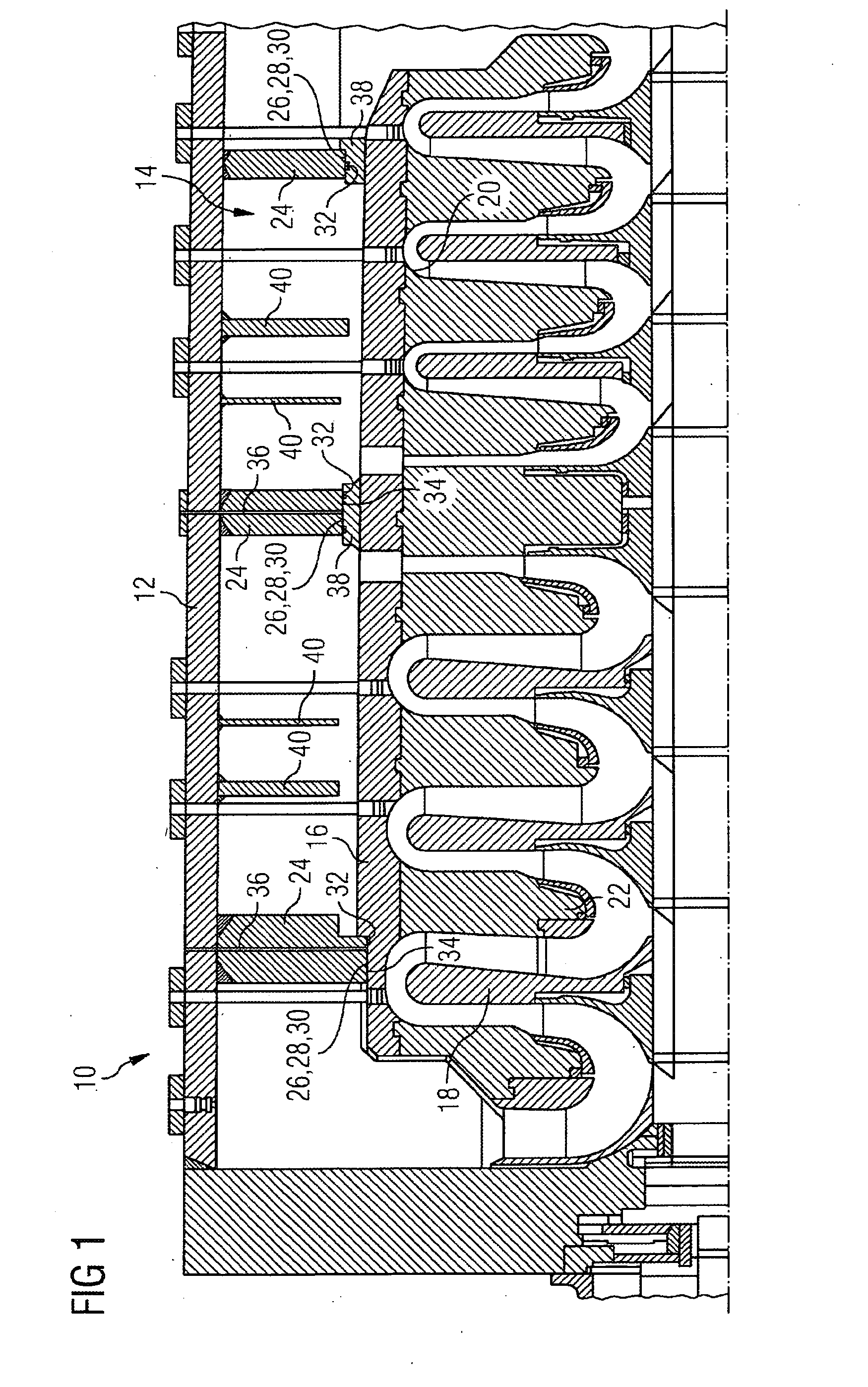
[0017]In FIG. 1, a turbocompressor 10 is shown in a half-sectional view. The turbocompressor 10 comprises an outer casing 12 in which a compressor unit 14 in the form of a bundle is arranged. The compressor unit 14 comprises an inner casing in the form of a tubular housing 16 in which a rotating wheel 18 is attached on a shaft 19. A stator element 22 is attached on the inner wall 20 of the tubular housing.

[0018]Three casing elements in the form of support walls 24 extend radially from the outer casing 12 and in the present case are also provided as partitions for different process stages. The compressor unit 14 is accommodated in a close fit in each case in three circular openings 26 which are formed in the support walls 24 and are axially oriented.

[0019]Between the inner wall 28 of the opening 26 which is formed in the support wall 24 which in FIG. 1 is arranged on the left, which inner wall is provided as a seat for the compressor unit 14, and the outer wall 30 of the tubular hous...


PUM


Abstract

A dynamic compressor, in particular a turbo compressor, having an exterior housing, a compressor unit featuring a tubular housing with an outer wall and a circular cross section, wherein the compressor unit is received by a circular opening which is located in the exterior housing and has an inner wall. Two compressor elements, which are at a distance from each other, are provided between the outer wall of the tubular housing and the inner wall of the opening in which the compressor unit is received, and wherein, furthermore, a fluid supply line is provided which penetrates the exterior housing and extends between the compressor elements which are at a distance from each other.

Description

CROSS REFERENCE TO RELATED APPLICATIONS[0001]This application is the US National Stage of International Application No. PCT / EP2007 / 054888 filed May 21, 2007 and claims the benefit thereof. The International Application claims the benefit of European application No. 06010926.1 EP filed May 26, 2006. Both of the applications are incorporated by reference herein in their entirety.FIELD OF INVENTION[0002]The invention relates to a dynamic compressor, especially a turbocompressor, with an outer casing and a compressor unit which has a tubular housing with an outer wall and a preferably circular cross section, wherein the compressor unit is accommodated in at least one preferably circular opening which is formed in the outer casing and has an inner wall.BACKGROUND OF INVENTION[0003]Compressor units in dynamic compressors, especially in turbocompressors, have to be centered in close fits. A fit which is formed insufficiently close results in the clearances which are required between rotati...

Claims


Application Information

Patent Timeline
Patent Type & Authority Applications(United States)
IPC IPC(8): F01D11/00
CPCF04D29/624F04D17/122
Inventor FINGERHUT, UDOZACHARIAS, WOLFGANG
Owner SIEMENS AG
Why Eureka
Try Eureka