
Flow-Deflecting Prosthesis for Treating Venous Disease

a flow-deflecting prosthesis and venous disease technology, applied in the field of flow-deflecting prosthesis for treating venous disease, can solve the problems of affecting the flow of blood to the heart, and affecting the function of the patient,

Active Publication Date: 2009-07-09
COOK MEDICAL TECH LLC
View PDF18 Cites 58 Cited by
  • Summary
  • Abstract
  • Description
  • Claims
  • Application Information

AI Technical Summary

Benefits of technology

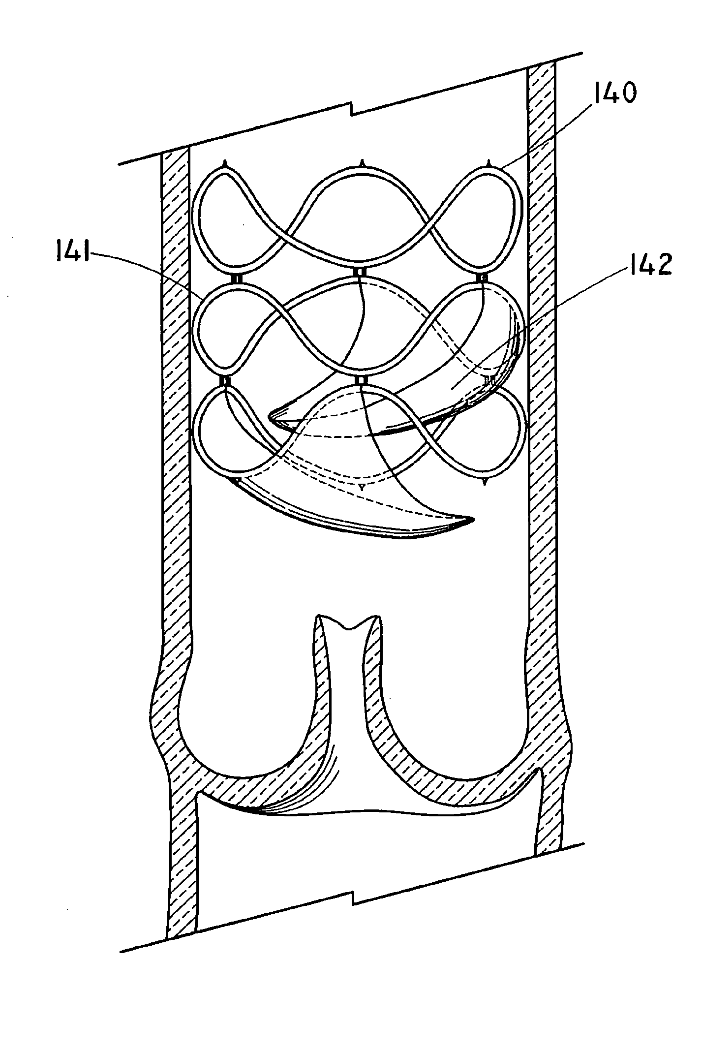
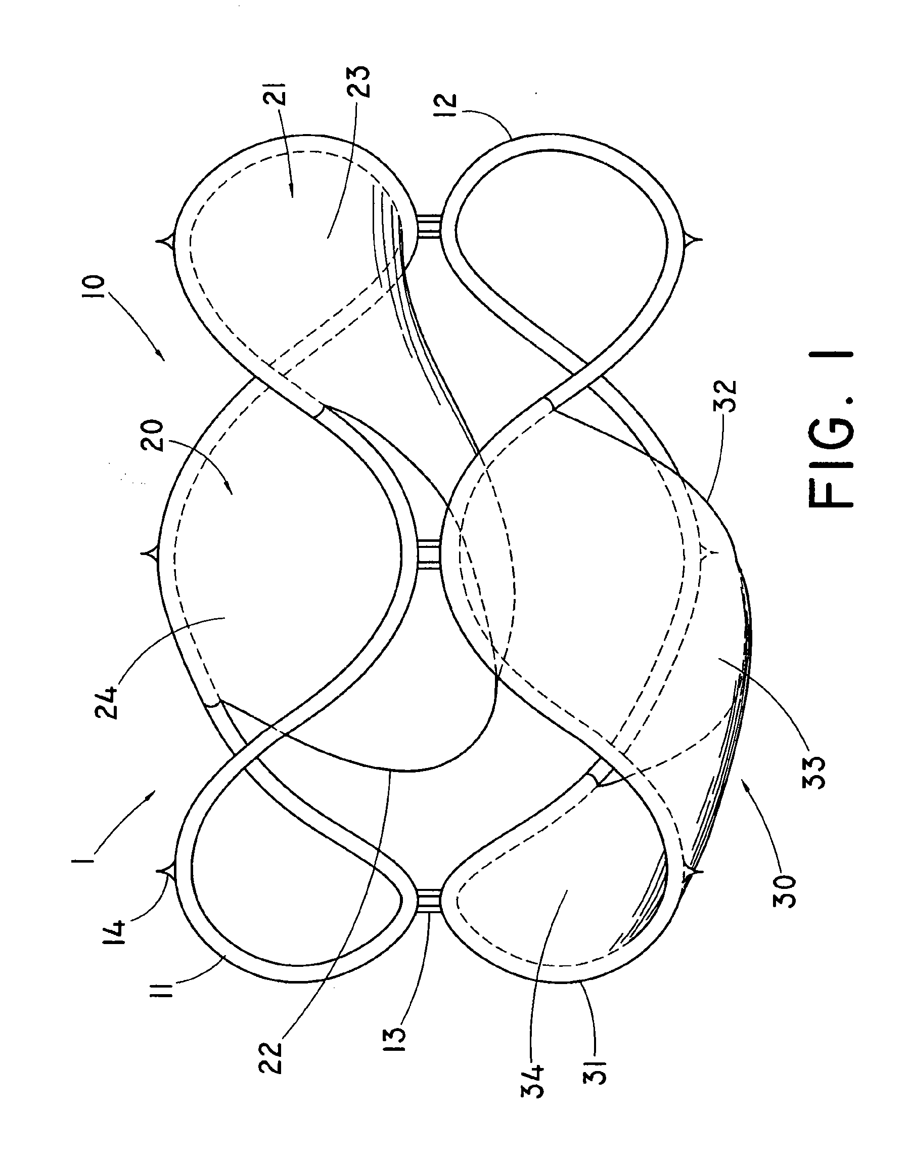
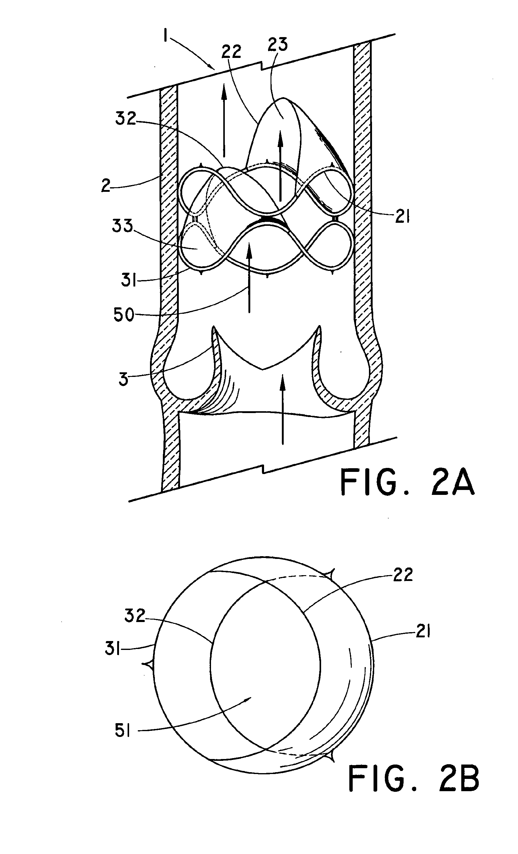
The present invention is a medical device that redirects retrograde flow onto a native valve in a body vessel. It consists of a support structure and a flow-deflecting member that can be everted between two positions. The device has an antegrade flow-receiving surface and a retrograde flow-receiving surface, which helps to deflect and redirect retrograde flow onto the native valve. This can improve the function and longevity of the valve. The method of treating a body vessel valve-related condition involves implanting the flow-deflecting medical device.

Problems solved by technology

When the leaflets of the bicuspid valves fail to close properly, the valves are considered “incompetent” as they permit leakage of retrograde flow resulting in the abatement of flow towards the heart.
While these can relieve symptoms, the underlying disease remains untreated.
Post-implantation thrombosis and platelet deposition on surfaces of endovascular prosthetic devices may occlude the conduit defined by the endovascular prosthesis or compromise the functionality of an implanted prosthetic valve by limiting the motion or responsiveness of moveable portions of the device.
For example, stagnation of blood around implanted prosthetic devices may lead to fibrin deposition and formation of thrombosis, reducing the devices' functionality and possibly eventually occluding the body lumen.

Method used


Image

  • Flow-Deflecting Prosthesis for Treating Venous Disease
  • Flow-Deflecting Prosthesis for Treating Venous Disease
  • Flow-Deflecting Prosthesis for Treating Venous Disease

Examples


Embodiment Construction

[0024]Unless otherwise defined, all technical and scientific terms used herein have the same meaning as commonly understood by one of ordinary skill in the art to which this disclosure pertains. In case of conflict, the present document, including definitions, will control. Preferred methods and materials are described below, although methods and materials similar or equivalent to those described herein can be used in the practice or testing of the present disclosure. All publications, patent applications, patents and other references mentioned herein are incorporated by reference in their entirety. The materials, methods, and examples disclosed herein are illustrative only and not intended to be limiting.

DEFINITIONS

[0025]The term “body vessel” means any tube-shaped body passage lumen that conducts fluid, including but not limited to blood vessels such as those of the human vasculature system, esophageal, intestinal, billiary, urethral and ureteral passages.

[0026]The term “biocompat...


PUM


Abstract

The disclosure relates to a flow-deflecting medical device comprising a support structure and at least one flow-deflecting member attached to the support structure. The flow-deflecting member is at least partially evertible between a first position and a second position. In the first position, antegrade flow contacts the antegrade surface of the flow-deflecting member, urging the flow-deflecting member proximally in the body vessel such that antegrade flow is substantially uninterrupted. In the second position, retrograde flow contacts the retrograde surface of the flow-deflecting member, urging the flow-deflecting member distally in the body vessel, such that retrograde flow is received and redirecting by the flow-deflecting member. Also provided is a method for treating a body vessel valve-related condition comprising implanting a flow-deflecting medical device proximal to a native valve.

Description

PRIORITY CLAIM[0001]This application claims the benefit of provisional U.S. Patent Application Ser. No. 61 / 019,751, filed Jan. 8, 2008, which is incorporated herein by reference in its entirety.BACKGROUND OF THE INVENTION[0002]The venous system includes a multitude of one-way bicuspid valves that permit substantially unidirectional blood to flow toward the heart. These valves are particularly important in the lower extremities to prevent the pooling of blood. When the leaflets of the bicuspid valves fail to close properly, the valves are considered “incompetent” as they permit leakage of retrograde flow resulting in the abatement of flow towards the heart.[0003]This potentially serious condition is known as “chronic venous insufficiency.” Symptoms can progress from unsightly “spider” or varicose veins to skin discoloration and painful skin ulcerations. The etiology of venous insufficiency is multifactorial, including a past history of thrombotic events, chronic venous stasis, and ve...

Claims


Application Information

Patent Timeline
Patent Type & Authority Applications(United States)
IPC IPC(8): A61F2/24A61F2/06
CPCA61F2/2418A61F2/2475A61F2220/0016A61F2220/0008A61F2002/068
Inventor AGNEW, CHARLES W.PAUL, JR., RAM H.
Owner COOK MEDICAL TECH LLC
Learn More