Method for the Onboard Determination of Train Detection, Train Integrity and Positive Train Separation

a technology of train integrity and onboard determination, applied in the field of railway safety, can solve the problems of inability to use in unsignaled areas, high installation and maintenance costs, and severe operational delays

Inactive Publication Date: 2009-07-09
LOCKHEED MARTIN CORP
View PDF6 Cites 32 Cited by
  • Summary
  • Abstract
  • Description
  • Claims
  • Application Information

AI Technical Summary

Benefits of technology

[0023]The method and system described herein adds a robustness that satisfies a higher safety classification (i.e., safety critical) relative to the prior art for operation on passenger and freight lines. And the method and system described herein provides train detection and integrity without the need for (1) expensive and high maintenance trackside equipment, such as track circuits and axle counters, or (2) an onboard end-of-train system.

Problems solved by technology

While axle counters can have a higher reliability than track circuits, when they fail or have an error condition, severe operational delays may be incurred in the process of re-establishing track occupancy for safe train operation.
While trackside systems have historically functioned well, they can be expensive to install and maintain.
Also, they cannot be used in un-signaled (“dark”) territories, thereby rendering areas of the track system without train detection functionality.
This requirement for additional signaling is disadvantageously accompanied by higher installation and operating costs.
In un-signaled (dark) territories, a rudimentary train integrity function could be performed by detecting a loss of brake-line pressure; however, the safety case for this method is limited.
The logistics in maintaining an end-of-train sensor on the last car are problematic.
Also, while monitoring brake line pressure is an approved method for detecting train pull-apart, that procedure alone does not meet the standard for a safety-critical determination.

Method used


Image

  • Method for the Onboard Determination of Train Detection, Train Integrity and Positive Train Separation
  • Method for the Onboard Determination of Train Detection, Train Integrity and Positive Train Separation
  • Method for the Onboard Determination of Train Detection, Train Integrity and Positive Train Separation

Examples


Embodiment Construction

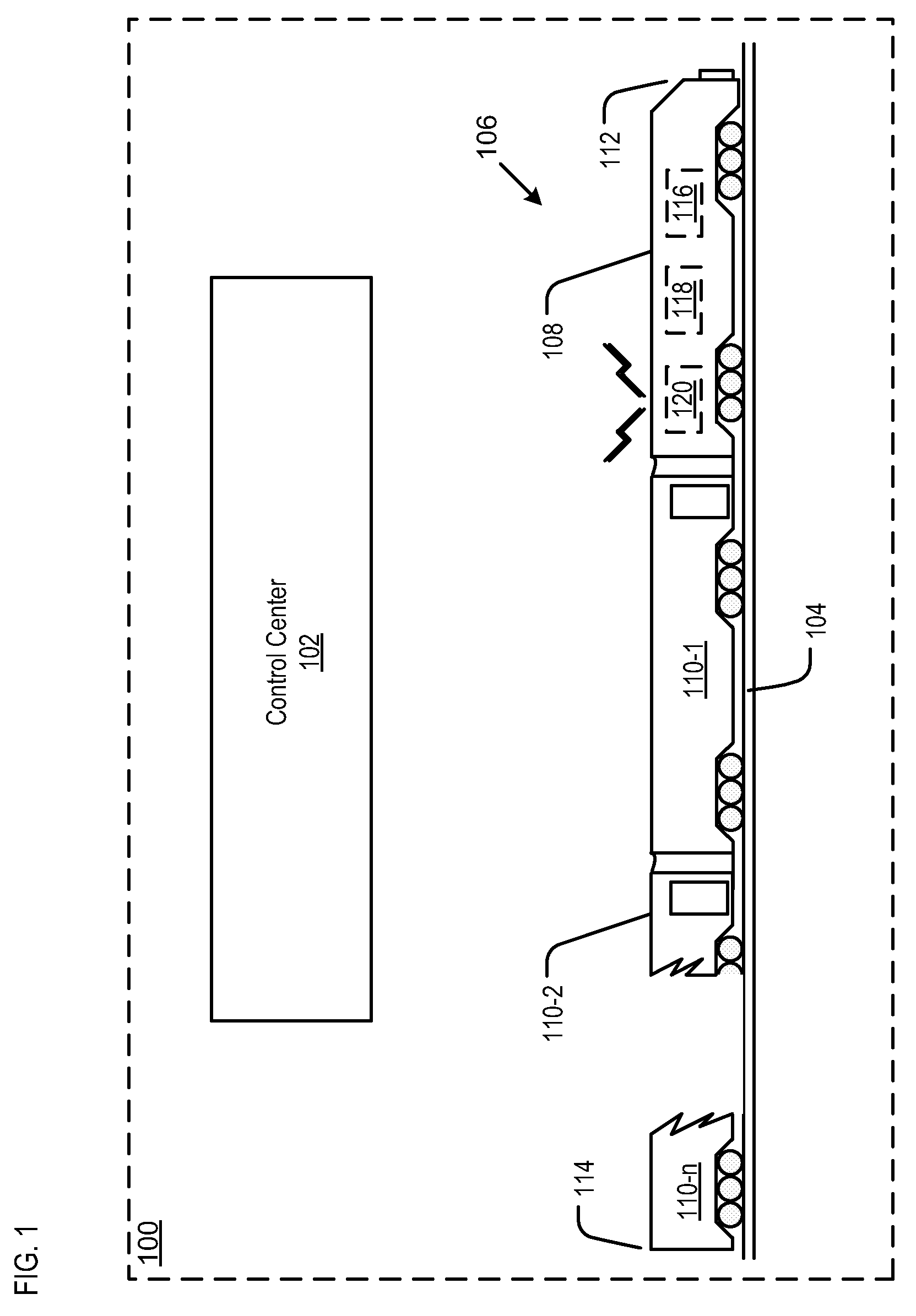
[0031]FIG. 1 depicts a portion of railway network 100. The portion of the network depicted in FIG. 1 includes control center 102, rail track 104, and train 106.

[0032]Control center 102 coordinates and manages train movements, monitors the operation of signaling and control systems, and receives (from trains, etc.) and develops information and reports regarding train performance, composition, and scheduling. In railway network 100, control center 102 is one of a plurality of distributed network control centers. In some other embodiments, a single control center is used to control the entire railway network.

[0033]Rail track 104 typically consists of two parallel steel rails, which are laid upon sleepers or cross ties that are embedded in ballast. The rail is fastened to the ties with rail spikes, lag screws or clips.

[0034]Train 106 comprises a plurality of connected rail vehicles that move along rail track 104 to transport freight or passengers from one place to another. In the illust...


PUM


Abstract

A system and method for onboard train detection is disclosed. In some embodiments, the train detection function is segregated into a safety-critical head-of-train determination, a safety-critical end-of-train (or length-of-train) determination, and a safety-critical train integrity function. By supplementing the train detection and integrity functions with information on system latencies, guard zones, processing delays and a determination of safe braking distance, the method and system provides safety-critical onboard positive train separation information. This information is transmitted to a control center and used to determine safe separation distance between trains.

Description

STATEMENT OF RELATED CASES[0001]This case claims priority of U.S. Provisional Patent Application 61 / 020,015, filed on Jan. 9, 2008 and incorporated by reference herein.FIELD OF THE INVENTION[0002]The present invention relates to railway safety in general, and, more particularly, to train detection, train integrity and positive train separation.BACKGROUND OF THE INVENTION[0003]Train “detection” is the safety-critical determination of the presence or absence of a train on a defined section (“block”) of a railway network. Once the block occupancy information is obtained, it is used in conjunction with track switch positions, etc., to determine route availability for trains.[0004]The location of a train in a railway network has historically been determined using trackside equipment, such as track circuits and / or axle counters. Track circuits are typically implemented by applying an electrical voltage to the track. The electrical voltage is sensed by trackside equipment only if no train ...

Claims


Application Information

Patent Timeline
Patent Type & Authority Applications(United States)
IPC IPC(8): G01C21/00G05D1/00
CPCB61L27/0038B61L15/0054B61L25/025B61L2205/04B61L27/20
Inventor JAMES, DEMETRIKLINCK, JR., WARREN H.
Owner LOCKHEED MARTIN CORP
Why Eureka
Try Eureka