Sealing device for elevator

a sealing device and elevator technology, applied in the direction of door/window accessories, transportation and packaging, door/window fittings, etc., can solve the problems of deteriorating the appearance of the elevator, exposing the residents to danger, and increasing the production cost, so as to achieve easy adjustment, small installation space, and high durability.

Inactive Publication Date: 2009-07-16
TOSHIBA ELEVATOR KK
View PDF12 Cites 0 Cited by
  • Summary
  • Abstract
  • Description
  • Claims
  • Application Information

AI Technical Summary

Benefits of technology

[0019]According to the present invention, there is provided a highly durable sealing device for an elevator door that is free of possibilities of wear-out of the seal member and an excessive frictional force, which requires a small installation space, easily adjustment and no wiring operation or a control device, and does not create an excessive reactive force or large noise of sliding when closing the door.
[0020]An embodiment of the sealing device according to the present invention includes a doorway member, a door, a movable member, a push down mechanism and a sealing mechanism. The doorway member is provided for a gate of an elevator. The door is provided adjacent to the doorway, and it is opened and closed with respect to the doorway member. The movable member is set horizontally and provided to be movable in a vertical direction for the doorway. The movable member is elastically urged upwards by urging means. The push-down mechanism pushes down the movable member downwards against the force of the urging means immediately before the door is closed after the door moves in the direction in which the door is closed. The sealing mechanism is maintained in a non-contact state with respect to the door when the door is moving, and seals the gap between the door and the doorway member as it is brought into contact with the upper section of the door by the operation of the movable member when it is pushed down by the push down mechanism.

Problems solved by technology

As a result, the smoke may spread to some other floors through the gap of the hall door of these floors, thus exposing the residents to danger.
However, when such smoke shutting facilities that include a shutter are provided, the production cost is naturally increased.
Further, the storage space and guide mechanisms that are provided afterwards deteriorate the appearance of the elevator.
On the other hand, in the upper section of the door and the doorsill portion, such seal member, if a rubber or a thin metal plate is simply mounted, entails the following problem.
Therefore, the seal member wears out or loses stiffness to deteriorate its smoke shutting performance.
Further, as the slide resistance is increased, the door can no longer be opened or closed smoothly or the noise created when the door slides may be increased.
Therefore, it is difficult to carry out the reform of adding the smoke shutting mechanism to an already installed door while retaining the measurements of the already installed door and its guide mechanism.
Furthers since the seal member is set inclined, it is difficult to appropriately adjust the pressing force and contact area both of the seal members provided for the doorstop of the door and the inclined seal member.
As a results it takes a lot of time and labor to adjust the seal member.
Consequently, it requires a large force to close the door and maintain the door closed.

Method used


Image

  • Sealing device for elevator
  • Sealing device for elevator
  • Sealing device for elevator

Examples


first embodiment

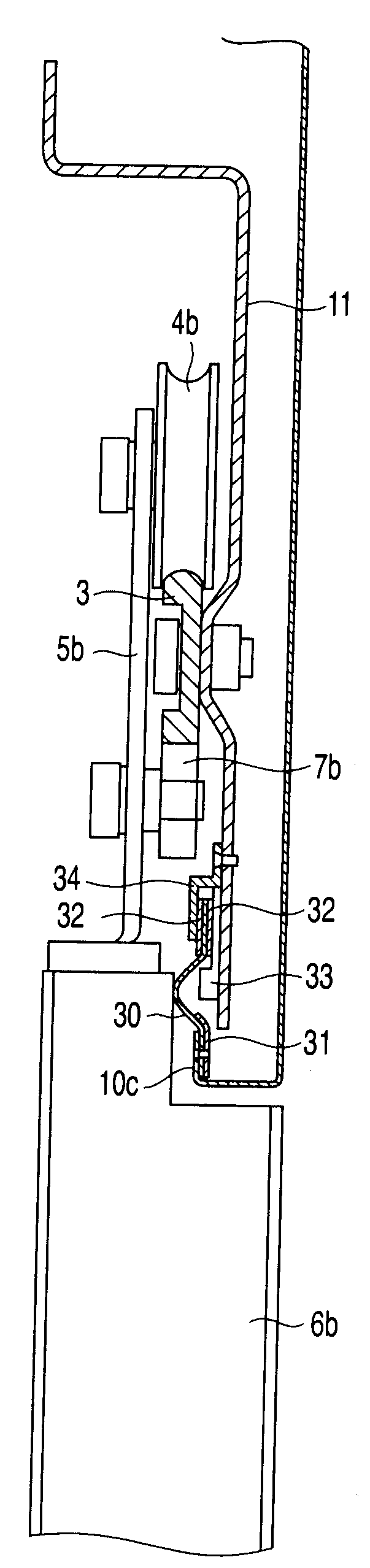
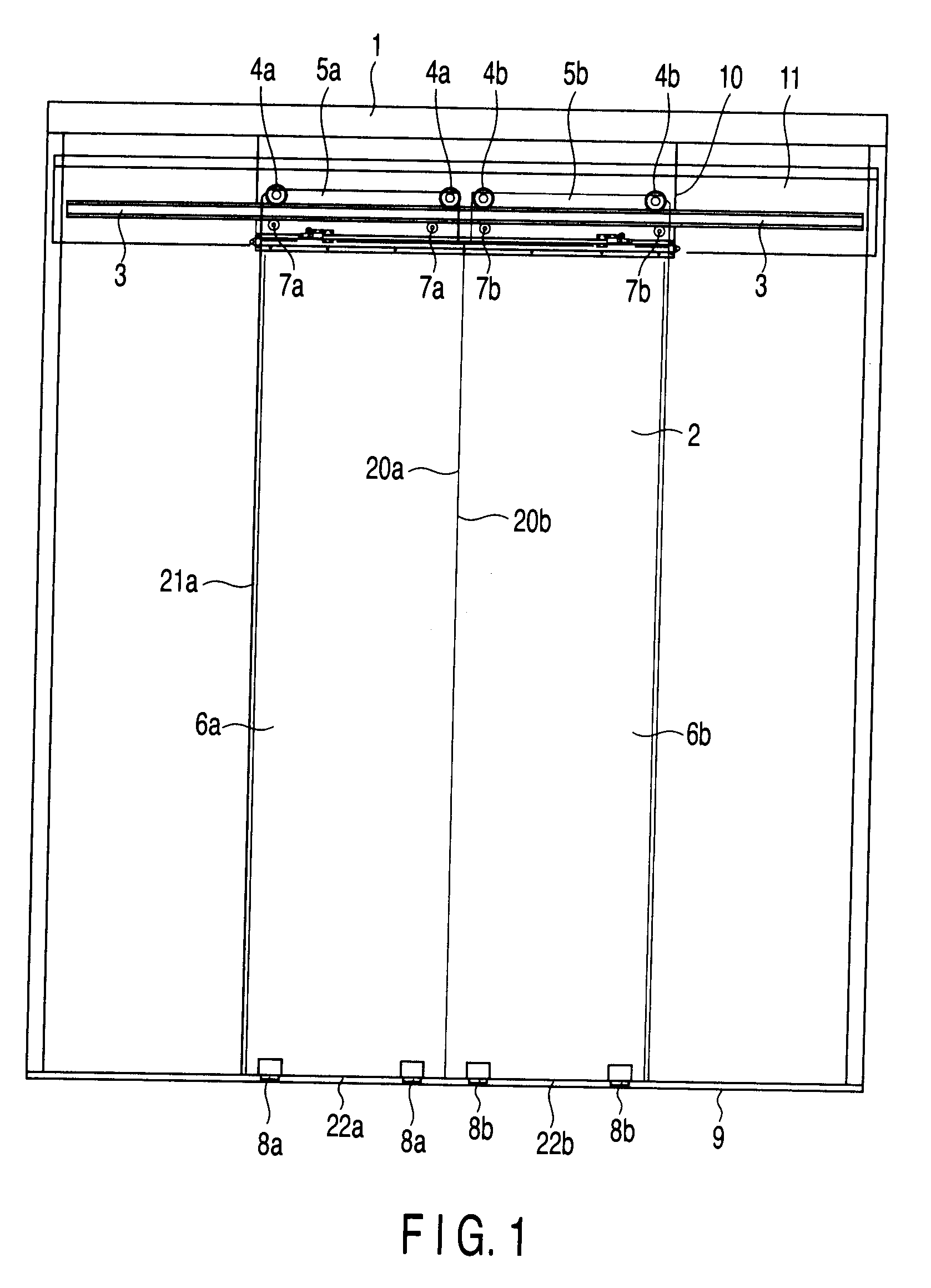
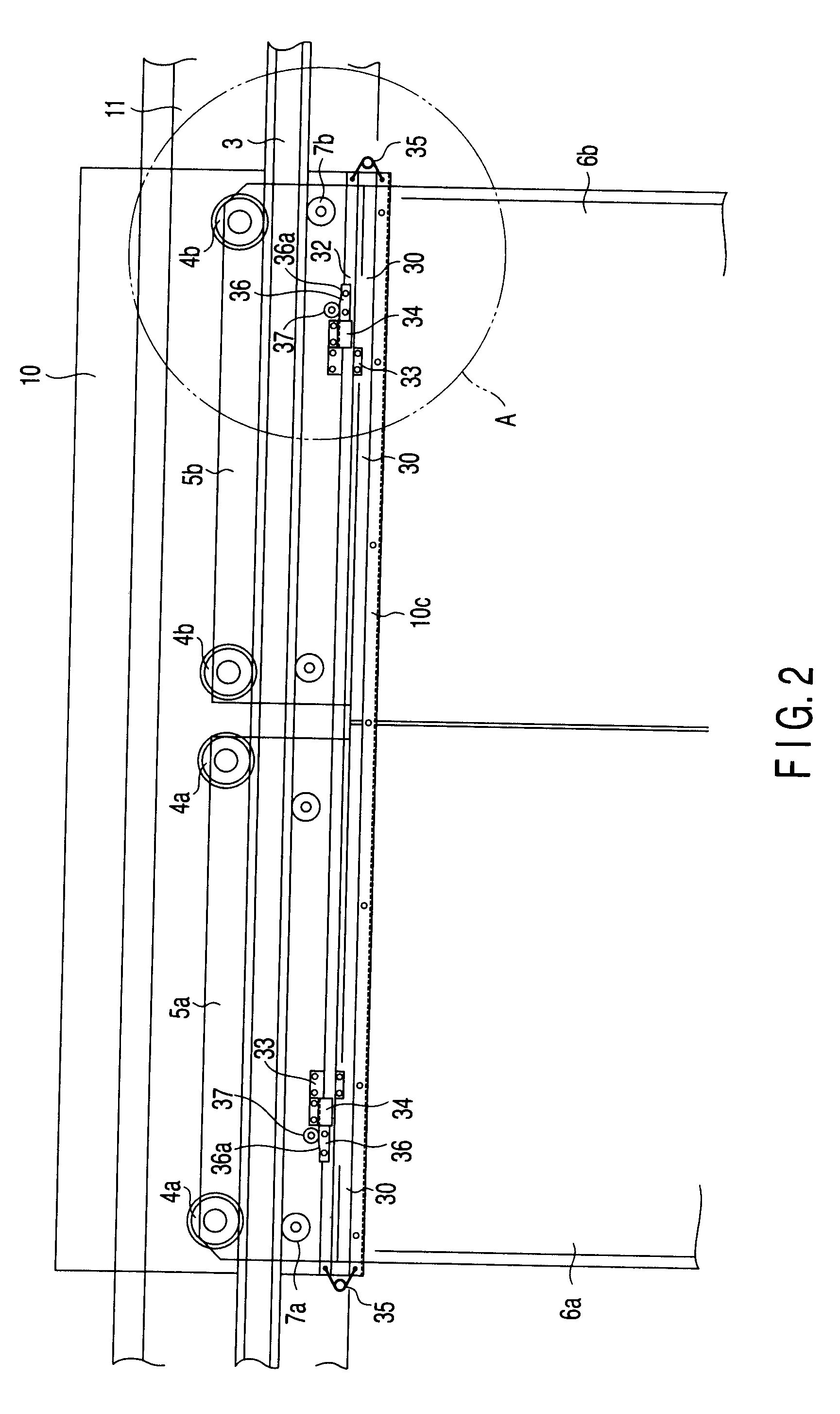
[0042]the present invention will now be described with reference to FIGS. 1 to 10. As shown in FIG. 1, a gate of an elevator comprises a frame body 1 serving as a doorway member to surround an opening portion 2 of an elevator shaft wall. A hanger rail 3 is installed in an upper section of the frame body 1 in a horizontal direction.

[0043]A pair of hall doors 6a and 6b are suspended from the hanger rail 3 by means of hanger rollers 4a and 4b and hangers 5a and 5b. The hall doors 6a and 6b move symmetrically to left and right along the hanger rail 3.

[0044]In order to prevent the hanger rollers 4a and 4b from coming off the rail, lower side support rollers 7a and 7b are arranged on the lower side of the hanger rail 3, and they are rotatably mounted on the hangers 5a and 5b, respectively.

[0045]The lower portions of the hall doors 6a and 6b are guided along a doorsill 9 provided to be substantially flush with the floor of the hall, by means of guide shoes 8a and 8b. Of the surrounding por...

second embodiment

[0060]the present invention will now be described in connection with a case where the present invention is applied to a door device of the one side sliding type with reference to FIGS. 8 to 12. FIG. 8 is a perspective front view of upper sections of hall doors 6c and 6d of the one side sliding type, viewed from the shaft side. FIGS. 9 to 12 are cross sectional views illustrating the structure of the door device with the respective parts. From FIGS. 9 to 12, the hall side is located on the right-hand side of the figure and the shaft side is located on the left-hand side of the figure.

[0061]As shown in FIG. 8, the low-speed hall door 6c and the high-speed hall door 6d are arranged to be displaced from each other in front and rear positions. FIG. 8 shows a state in which the hall doors 6c and 6d are closed. While opening the hall doors 6c and 6d from this state, the low-speed hall door 6c moves at a low speed towards a door case 50 on the left-hand side of the figure, and the high-spee...

third embodiment

[0083]the present invention will now be described with reference to FIGS. 13 and 14. FIG. 13 is a cross sectional view illustrating the upper section of the hall door 6e while it is not completely closed, and FIG. 14 is a cross sectional view illustrating the upper section of the hall door 6e when it is completely closed.

[0084]A belt-like fluorine-based rubber sheet 60 is provided horizontally on the folded portion 14c of the door header 14 to extend along the longitudinal direction of the folded portion 14c. The lower end portion of the rubber sheet 60 is pinched between the lower holder plate 61 and the folded portion 14c to be fixed to the folded portion 14c. The upper end portion of the rubber sheet 60 is extended above the folded portion 14c to face the upper section of the hall door 6e.

[0085]The back support plate 33 and front support plate 34, each formed of a synthetic resin, are attached to the inner surface of the lower end portion of the header case 11. A holder plate 62...


PUM


Abstract

A sealing device for an elevator door includes a doorway member, doors, a movable member, a push-down mechanism and a sealing mechanism. The doorway member is provided for a gate. The doors open or close along the doorway member. The movable member is set horizontally and provided to be movable in a vertical direction in the doorway member, and it is urged upwards by an urging unit. The push-down mechanism pushes down the movable member against the force of the urging unit just before the doors are closed. The sealing mechanism is kept non-contact with the doors while they are moving, and seals the gap between the doors and the doorway member as it is brought into contact with upper section of the doors when the movable member is pushed down by the push-down mechanism.

Description

CROSS-REFERENCE TO RELATED APPLICATIONS[0001]This is a Continuation Application of U.S. Ser. No. 11 / 203,090, filed Aug. 15, 2005, which is a continuation of PCT Application No. PCT / JP2004 / 010372, filed Jul. 14, 2004, which was published under PCT Article 21(2) in English. The entire contents of both of these applications are incorporated herein by reference.[0002]This application is based upon and claims the benefit of priority from prior Japanese Patent Application No. 2003-202455, filed Jul. 28, 2003, the entire contents of which are incorporated herein by reference.BACKGROUND OF THE INVENTION[0003]1. Field of the Invention[0004]The present invention relates to a sealing device for an elevator, which seals a gap between a doorway member provided in the gate of an elevator and a door device provided adjacent to the doorway member.[0005]2. Description of the Related Art[0006]The gate of an elevator is provided between an elevator hall in a building and an elevator shaft. The doorway...

Claims


Application Information

Patent Timeline
Patent Type & Authority Applications(United States)
IPC IPC(8): E06B7/16E06B3/00B66B13/30
CPCB66B13/308B66B13/30B66B13/00B66B13/06B66B13/08
Inventor MURAKAMI, SHINKINOSHITA, TORU
Owner TOSHIBA ELEVATOR KK
Why Eureka
Try Eureka