Differential pressure assemblies and methods of using same

a technology of differential pressure and assembly, applied in the direction of liquid/fluent solid measurement, instrumentation, clear air turbulence detection/forecasting, etc., can solve the problems of aircraft being prone to severe hazards, difficult to measure frequency range, aircraft repair and downtime,

Inactive Publication Date: 2009-07-16
HONEYWELL INT INC
View PDF10 Cites 10 Cited by
  • Summary
  • Abstract
  • Description
  • Claims
  • Application Information

AI Technical Summary

Benefits of technology

[0006]The present invention generally relates to a differential pressure sensor assembly capable of measuring small pressure variations over the desired range of frequencies for the detection of turbulence, even during large pressure changes in an ambient environment in which the differential pressure sensor assembly is located. In addition, the differential pressure sensor assembly may further detect a phase of infrasound spectral pressure frequencies associated with the small pressure variations which are associated with an atmospheric turbulence condition.

Problems solved by technology

Clear air turbulence updrafts, downdrafts, and convective air flows all present severe hazards to aircraft.
Effects on aircraft encountering any of these hazards range from severe buffeting to a structural or mechanical failure of one or more airplane components.
These sounds are in a frequency range that is difficult to measure with current pressure sensors and related microphone technology.
The costs resulting from flight vehicles that encounter clear air turbulence may include aircraft repair and downtime, crew injuries and passenger injuries.
Radar cannot detect clear air turbulence because it is composed of clear air which does not contain reflecting aerosols.
An experimental LIDAR system, however, has generated clear air turbulence warnings of only a few seconds.
One drawback of using conventional pressure sensors to detect atmospheric turbulence is that they should achieve a requisite level of sensitivity over the frequency range of interest.
Absolute pressure sensors do not have the requisite level of sensitivity and conventional differential pressure sensors have a limited pressure range over which they can achieve accurate and consistent measurements of the differential pressure.
However, when the differential pressure across the diaphragm is greater than 125 Pascals, the Honeywell DC001NDR5 differential pressure sensor may become saturated and thus essentially inoperative.
Because the ambient pressure will change by much more than the 125 Pascals, the attempted approach of sealing off one side of the differential pressure sensor has been shown to be inadequate.

Method used


Image

  • Differential pressure assemblies and methods of using same
  • Differential pressure assemblies and methods of using same
  • Differential pressure assemblies and methods of using same

Examples


Embodiment Construction

[0014]In the following description, certain specific details are set forth in order to provide a thorough understanding of various embodiments of the invention. However, one skilled in the art will understand that the invention may be practiced without these details or with various combinations of these details. In other instances, well-known structures and methods associated with pressure sensors, microphones and methods of making and using the same may not be shown or described in detail to avoid unnecessarily obscuring descriptions of the embodiments of the invention.

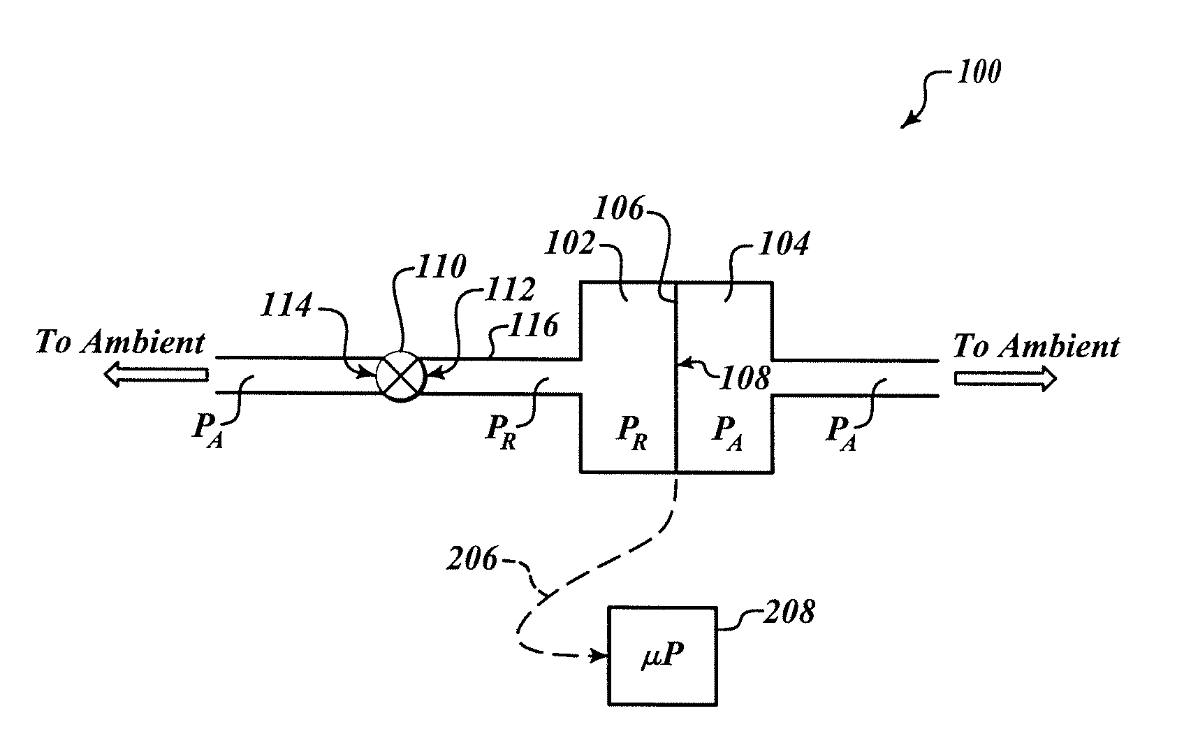
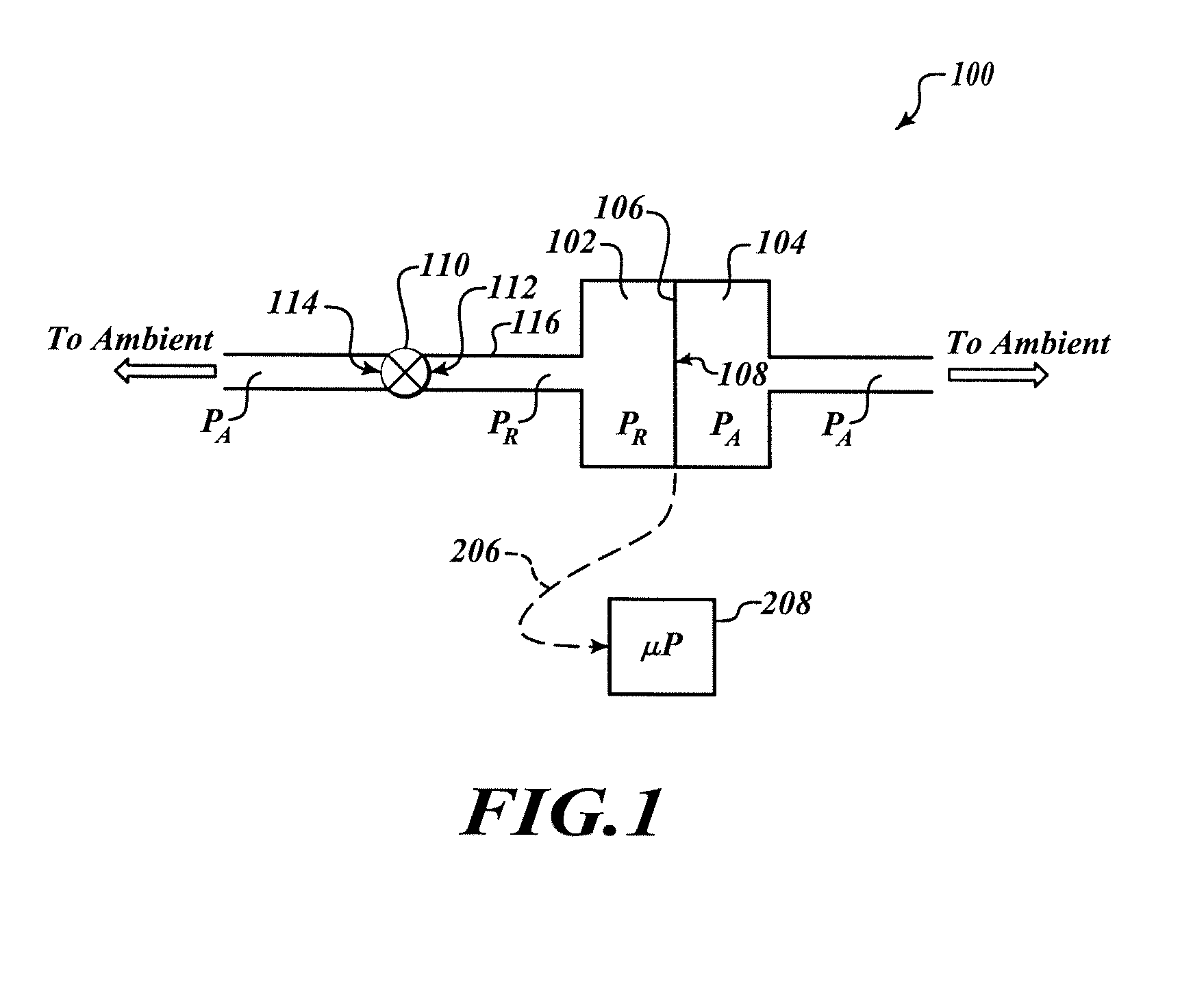
[0015]The following description is generally directed to differential pressure sensor assemblies and methods for detecting and measuring infrasound, which is generally characterized as sound produced at frequencies below 20 Hertz (Hz). Specifically, the differential pressure sensor assemblies and methods may be useful for the detection of atmospheric turbulence that may endanger an airliner or other flight vehicle. T...


PUM


Abstract

Differential pressure sensor assemblies for detecting and measuring infrasound, which is generally characterized as sound produced at frequencies below 20 Hertz (Hz). Specifically, the differential pressure sensor assemblies may form part of a detection system for clear air turbulence or other atmospheric turbulence. The differential pressure sensor assemblies detect a differential pressure across a flexible diaphragm that separates an ambient pressure chamber from a reference pressure chamber. In one embodiment, the pressure in the reference chamber may be controlled using a valve that may be selectively opened and closed. In another embodiment, the pressure in the reference chamber may be controlled using a static, structural member with a plurality of small openings that permits the reference chamber to be in continuous fluid communication with an ambient environment.

Description

BACKGROUND OF THE INVENTION[0001]Clear air turbulence updrafts, downdrafts, and convective air flows all present severe hazards to aircraft. Effects on aircraft encountering any of these hazards range from severe buffeting to a structural or mechanical failure of one or more airplane components.[0002]U.S. Pat. No. 6,480,142 issued to W. L. Rubin describes a system for detecting such hazards with the utilization of Doppler shifted frequencies of received radar signals backscattered from sound generated by atmospheric turbulent flows. The radiated radar signals are generally within the ultra-high frequency (UHF) or microwave bands. W. L. Rubin further describes how the sound, in a frequency range of about 0.1-20 Hertz (Hz), generated by atmospheric turbulent flows can be used to detect the presence of the turbulence. These sounds are in a frequency range that is difficult to measure with current pressure sensors and related microphone technology.[0003]Clear air turbulence, a subset of...

Claims


Application Information

Patent Timeline
Patent Type & Authority Applications(United States)
IPC IPC(8): G01F1/38
CPCG01W1/00G01W2001/003Y02A90/10
Inventor MCKITTERICK, JOHN B.HORAK, DAN T.
Owner HONEYWELL INT INC
Why Eureka
Try Eureka