High Flow Capacity Positioner

a positioner and high flow technology, applied in the field of fluid flow control, can solve problems such as unbalanced position of spools, and achieve the effect of reducing spool displacemen

Active Publication Date: 2009-07-16
SUBARU TECNICA INTERNATIONAL
View PDF11 Cites 13 Cited by
  • Summary
  • Abstract
  • Description
  • Claims
  • Application Information

AI Technical Summary

Benefits of technology

[0018]The present invention specifically addresses and alleviates the above-identified deficiencies in the art. In this regard, the present invention is directed to a spool manifold assembly for operative coupling to a valve positioner. The spool manifold assembly is used to port fluid to and from a valve closure element such as an actuator. The spool manifold assembly includes a housing having a plurality of openings for receiving and exhausting air flowing from a plurality of fluid flow passageways. The plurality of openings on the housing are substantially aligned with the plurality of fluid flow passageways when the spool manifold assembly is coupled to the valve positioner. A tubular sleeve is disposed within the housing. The tubular sleeve includes a plurality of apertures configured to receive fluid flowing from corresponding ones of the fluid flow passageways. The spool manifold assembly also includes a spool disposed within the tubular sleeve. The spool slides axially along a longitudinal axis to port fluid to the fluid flow passageways and an exhau

Problems solved by technology

However, if the pressure against the diaphragm is either increased or decreased to the point wher

Method used


Image

  • High Flow Capacity Positioner
  • High Flow Capacity Positioner
  • High Flow Capacity Positioner

Examples


Embodiment Construction

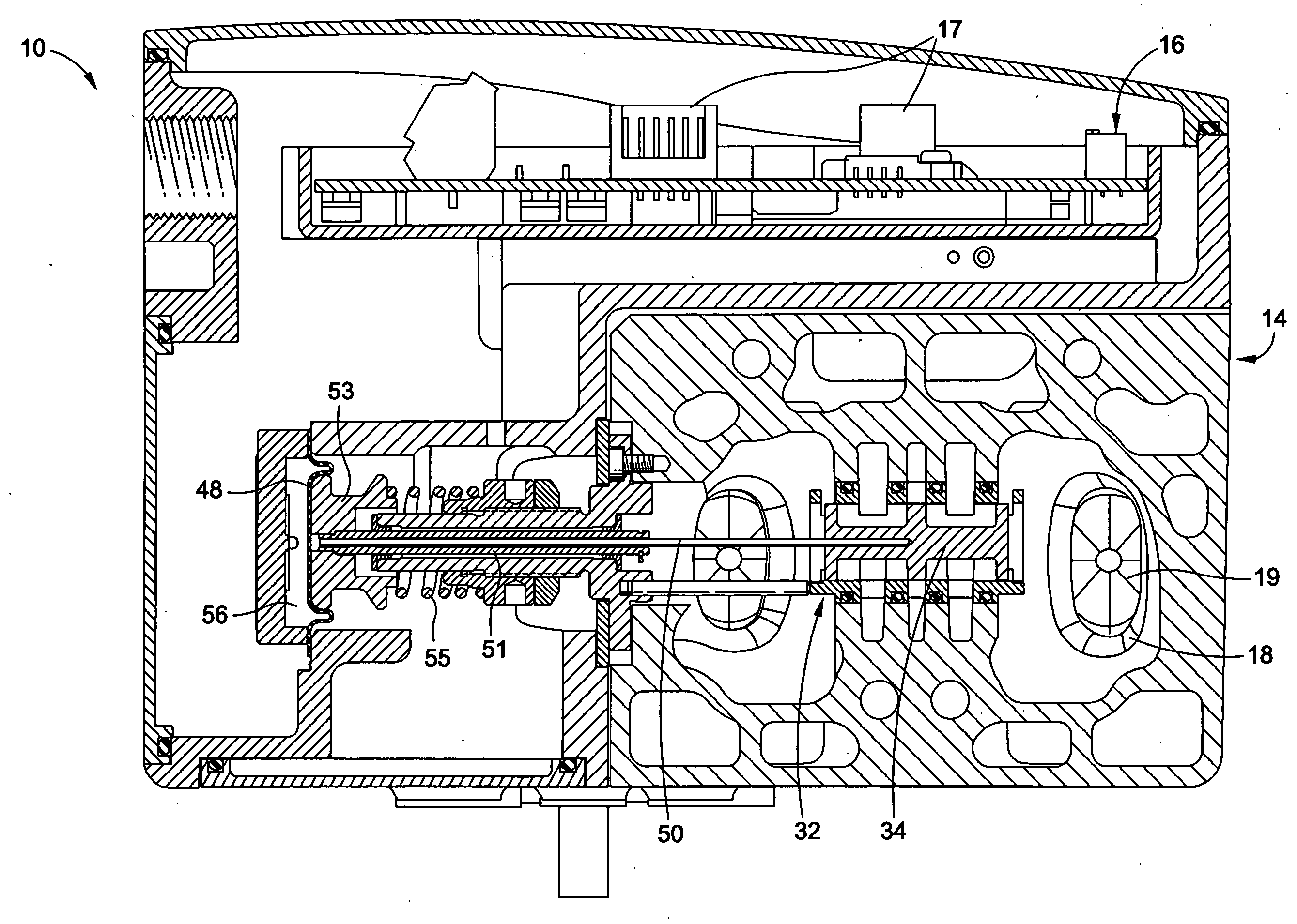
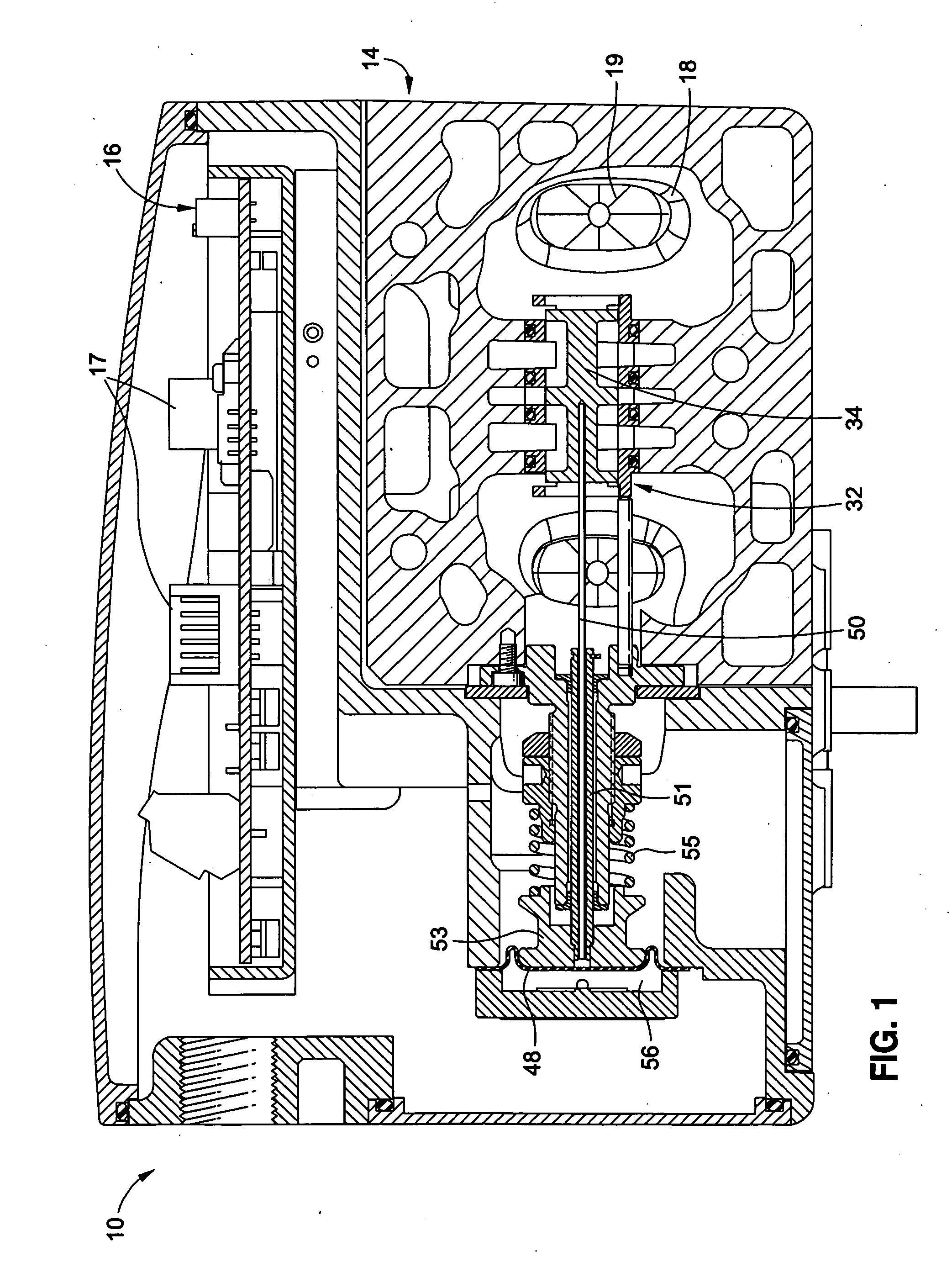
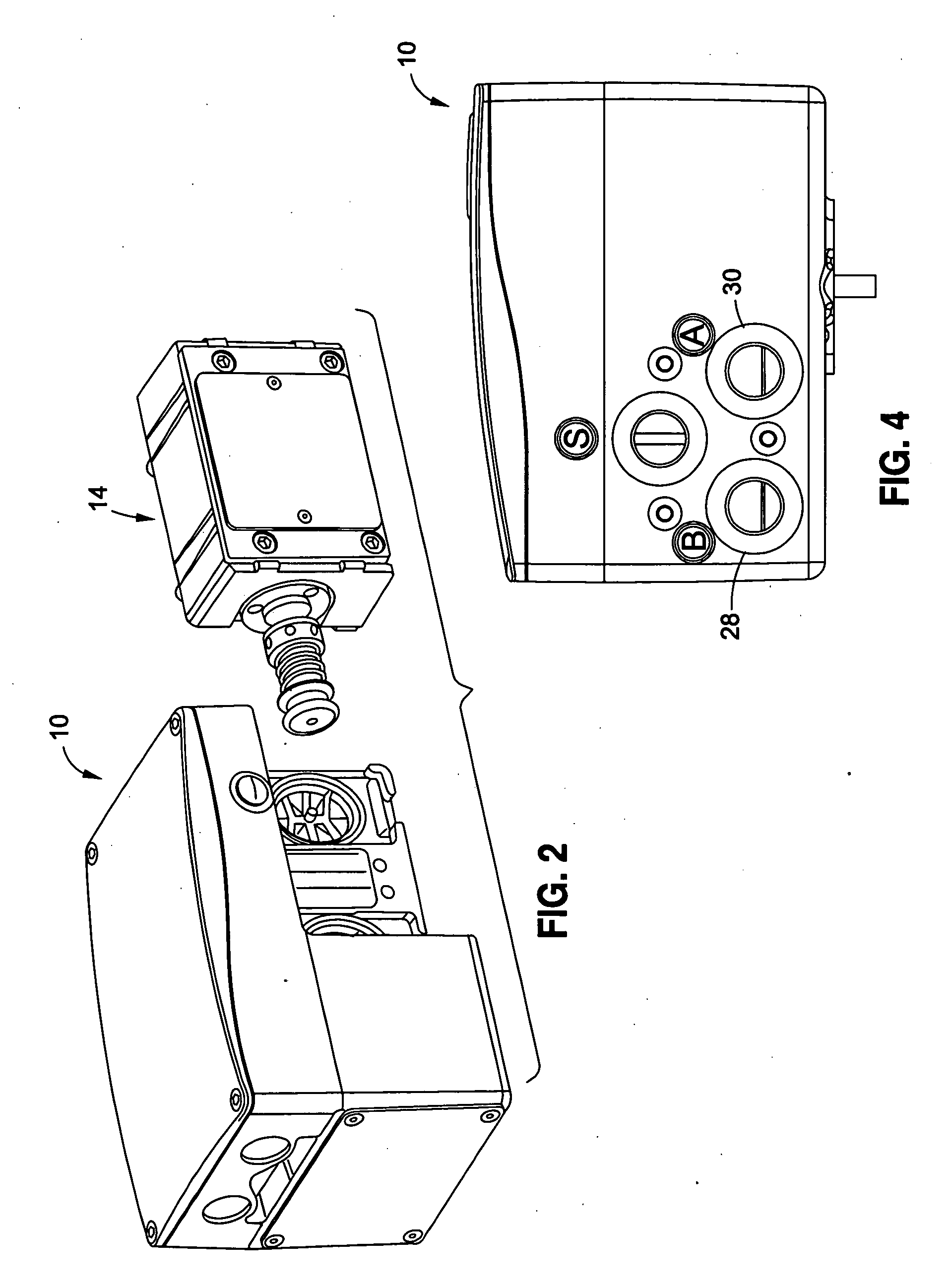
[0038]Referring now to the drawings wherein the showings are for purposes of illustrating an embodiment of the present invention and not for purposes of limiting the same, FIG. 1 illustrates a positioner 10 constructed in accordance with the present invention. The positioner 10 includes a spool manifold assembly 14, and a printed circuit board (PCB) assembly 16 incorporating electrical components 17. The role of the positioner 10 is that of a position controller (servomechanism) that is mechanically connected to an actuator (not shown). The positioner 10 is configured to adjust its output to the actuator to maintain a desired position of the actuator in proportion to an input current signal. Therefore, the positioner 10 is employed to provide the motive force necessary to displace the actuator to a desired position in order to open or close the valve to which the actuator is connected to.

[0039]The spool manifold assembly 14 is an integral part of the positioner 10. The spool manifol...


PUM


Abstract

A valve positioner for controlling a valve closure element is provided. The positioner includes a positioner housing with a plurality of fluid flow passageways in fluid communication with a fluid supply source and the valve closure element. The positioner housing is configured to receive a detachable spool manifold assembly. The spool manifold assembly is positioned adjacent the plurality of fluid flow passageways. The spool manifold assembly includes a reciprocally moveable spool configured to selectively port fluid flow from the plurality of fluid flow passageways. The spool manifold assembly includes a diaphragm connected to the spool via a flexible shaft. The diaphragm is in fluid communication with a transducer for receiving a fluid causing the diaphragm to expand or contract and thereby displacing the spool. The flexible shaft is radially elastic in order to minimize axial backlash between the diaphragm and the spool. The flexible shaft configuration minimizes the spool stroke.

Description

CROSS-REFERENCE TO RELATED APPLICATIONS[0001]The present application claims priority to U.S. Provisional Application No. 61 / 011,035 filed Jan. 14, 2008, the disclosure of which is incorporated herein by reference.STATEMENT RE: FEDERALLY SPONSORED RESEARCH / DEVELOPMENT[0002]Not ApplicableBACKGROUND OF THE INVENTION[0003]1. Technical Field of the Invention[0004]The present invention relates generally to fluid flow control and, more particularly, to a high flow capacity positioner for regulating fluid flow within a fluid circuit.[0005]2. Description of the Related Art[0006]A control valve regulates a flowing fluid, such as gas, steam, water, or chemical compounds. An actuator may be used to regulate the flow of fluid within a control valve. The actuator provides motive power to open or close the valve and therefore regulate the fluid flow within the valve.[0007]A valve positioner is a device mounted on the actuator that may implement a control strategy determined by an output of a contr...

Claims


Application Information

Patent Timeline
IPC IPC(8): G05D11/00F16K11/18
CPCF16K31/426Y10T137/2652Y10T137/0324Y10T137/87716Y10T137/8671Y10T137/8778Y10T137/8663Y10T137/86831Y10T137/2531F15B13/0402F15B2211/3116F15B2211/327F15B2211/329F15B2211/6313F15B2211/6336F15B2211/6656F15B2211/75F15B2211/7656F15B2211/8855F15B5/006F15B13/0433
Inventor TONDOLO, FLAVIO
Owner SUBARU TECNICA INTERNATIONAL
Why Eureka
Try Eureka