
Cooler module without base panel

a cooler module and base panel technology, applied in the field of cooler modules, can solve the problems of increasing the cost, complex mounting procedure, and not meeting environmental protection requirements, and achieve the effect of eliminating the use of a base panel, saving material costs, and quick dissipation

Active Publication Date: 2009-07-16
HUANG TSUNG HSIEN
View PDF11 Cites 27 Cited by
  • Summary
  • Abstract
  • Description
  • Claims
  • Application Information

AI Technical Summary

Benefits of technology

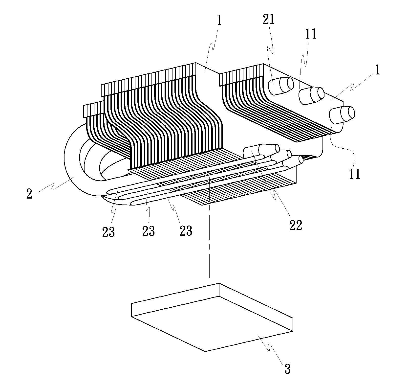
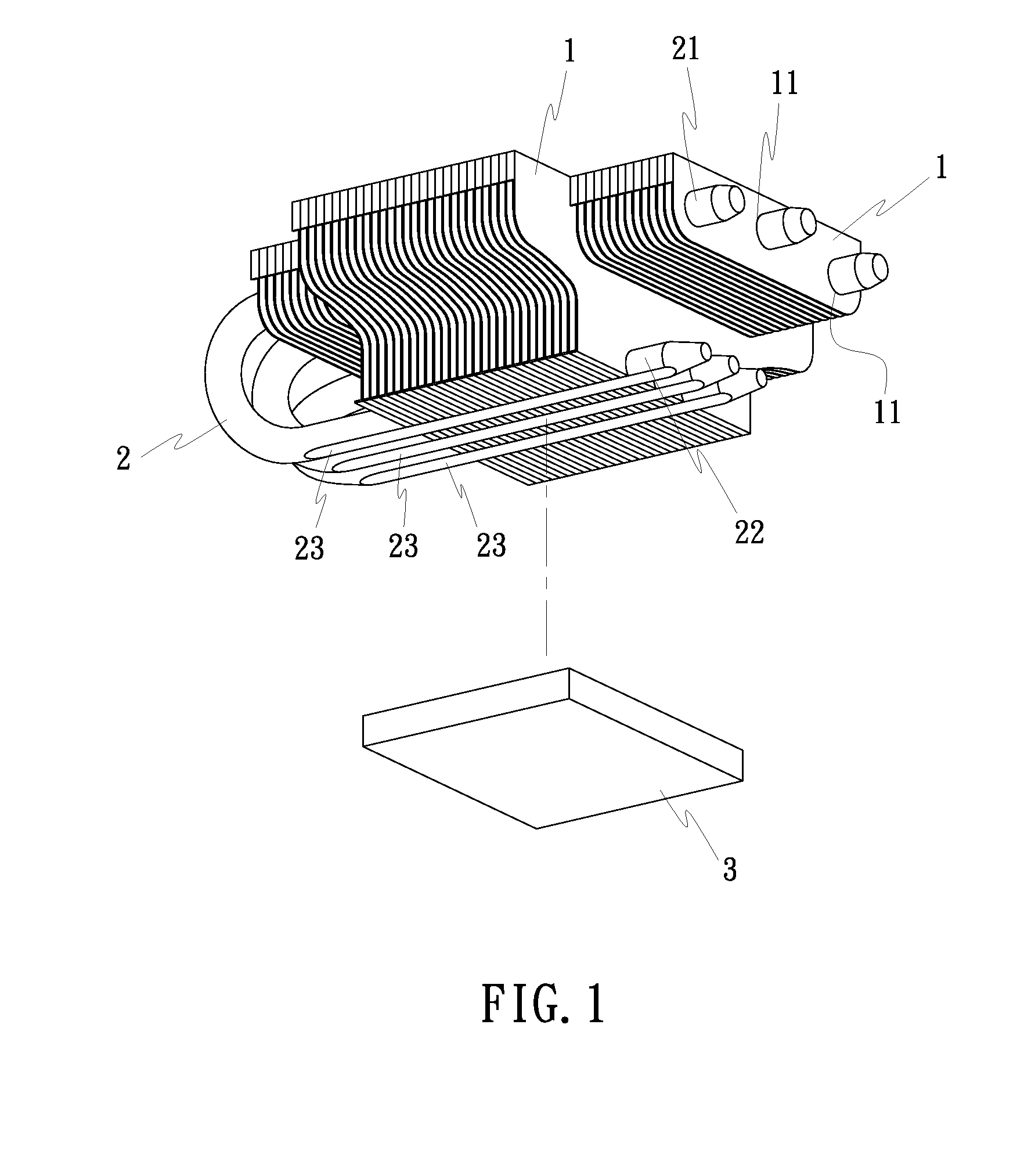
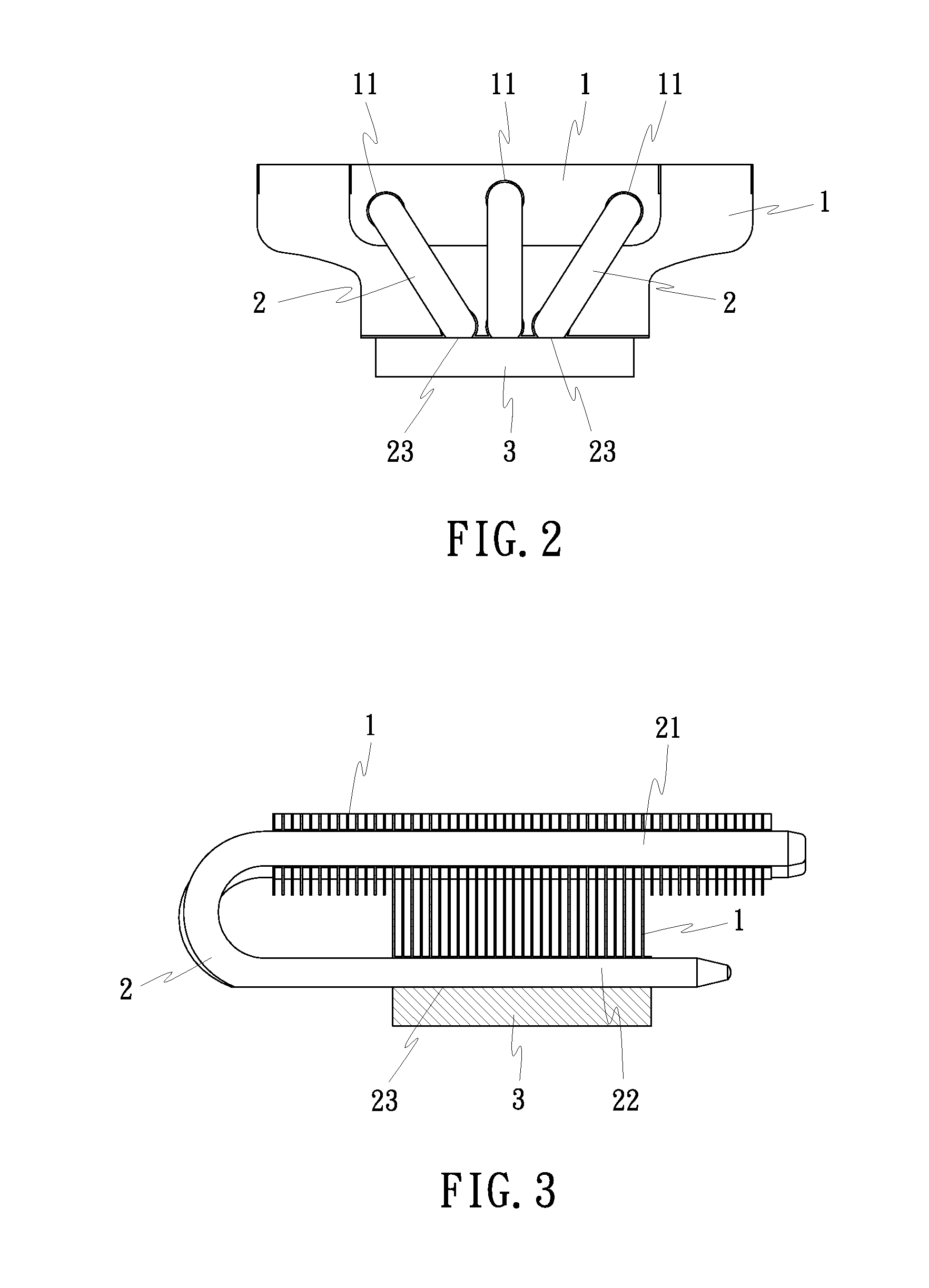
[0007]The present invention has been accomplished under the circumstances in view. According to one aspect of the present invention, the cooler module comprises a plurality of radiation fins, and a plurality of heat pipes fastened to the radiation fins to hold the radiation fins in parallel. Each heat pipe has a flat bottom surface portion exposed to the outside of the radiation fins for bonding to a semiconductor device for enabling the heat pipes to transport heat from the semiconductor device to the radiation fins for quick dissipation. Because the cooler module eliminates the use of a base panel, saving much the material cost and greatly reducing the size to facilitate packing and delivery.

Problems solved by technology

This mounting procedure is complicated, increasing the cost.
Further, the bonding process is not in conformity with environmental protection requirements.
Because the base panel is a solid metal block, the heat sink is big and heavy, and the material cost for the heat sink is high.
Therefore, the aforesaid conventional cooler module cannot quickly dissipate heat at the beginning.

Method used


Image

  • Cooler module without base panel
  • Cooler module without base panel
  • Cooler module without base panel

Examples


first embodiment

[0032]Referring to FIGS. 1˜4, a cooler module in accordance with the present invention is a horizontal design, comprised of a plurality of radiation fins 1 and a plurality of heat pipes 2.

[0033]The radiation fins 1 are arranged in a stack, forming a block-like radiation fin module. The radiation fins 1 may be made in any of a variety of sizes and shapes for horizontal mounting. Each radiation fin 1 has a plurality of horizontal through holes 11 horizontally cut through two opposite sides thereof and a plurality of bottom notches 12 arranged in parallel on the bottom side thereof for the mounting of the heat pipes 2.

[0034]The heat pipes 2 are sealed hollow U-pipes filled with a working fluid, each having a first end pipe section 21 and a second end pipe section 22. The first end pipe section 21 is tightly inserted through one respective horizontal through hole 11 of each of the radiation fins 1. The second end pipe section 21 is press-fitted into one respective bottom notch 12 of eac...

third embodiment

[0040]FIGS. 9 and 10 show a cooler module in accordance with the present invention. This third embodiment is a horizontal design. According to this third embodiment, the cooler module is comprised of a plurality of radiation fins 1, two side plates 41 and 42, and a plurality of heat pipes 2. The radiation fins 1 are arranged in a stack and set between the two side plates 41 and 42. The heat pipes 2 are U-pipes, each having a first end pipe section 21 respectively fastened to the side plates 41 and 42 and the radiation fins 1 and a second end pipe section 22 fastened to the side plates 41 and 42 and suspending below the radiation fins 1. The second end pipe section 22 of each heat pipe 2 has a flat bottom surface portion 23 kept in positive contact with the top surface of a semiconductor chip, for example, CPU 3.

[0041]FIGS. 11 through 13 show a cooler module in accordance with a fourth embodiment of the present invention. This fourth embodiment is a horizontal design. According to th...

fifth embodiment

[0044]FIGS. 14 and 15 show a horizontal type cooler module in accordance with the present invention. According to this fifth embodiment, the radiation fin module of the radiation fins 1 has two horizontal through holes (not shown) for the mounting of two locating bars 13, and a mounting frame 14 is used with the locating bars 13 to affix the cooler module in place, keeping the flat bottom surface portions 23 in positive contact with the hotter interface (CPU) 3.


PUM


Abstract

A light, compact, non-bottom panel type cooler module includes a plurality of radiation fins arranged in a stack, and a plurality of U-shaped heat pipes fastened to the radiation fins to hold the radiation fins in parallel, each U-shaped heat pipe having one or two opposite end pipe sections thereof press-fitted into respective through holes on the radiation fins and a flat bottom surface portion exposed to the outside of the radiation fins for bonding to a semiconductor device for enabling the heat pipes to transport heat from the semiconductor device to the radiation fins for dissipation.

Description

BACKGROUND OF THE INVENTION[0001](a) Field of the Invention[0002]The present invention relates to cooler modules and more particularly, to a light, compact, non-base panel type cooler module formed of radiation fins and heat pipes, wherein each heat pipe has a flat bottom surface portion exposed to the outside of the radiation fins for bonding to a semiconductor device to transport heat from the semiconductor device to the radiation fins for quick dissipation.[0003](b) Description of the Prior Art[0004]A conventional cooler module is known comprising a heat sink and a plurality of heat pipes fastened to the heat sink. The heat sink comprises a base panel and a plurality of radiation fins extended from the base panel. The base panel is made out of copper or aluminum, and adapted for transporting heat from, for example, a semiconductor chip to the radiation fins for quick dissipation into the outside open air. The radiation fins are extruded from aluminum or copper. The heat pipes are...

Claims


Application Information

Patent Timeline
Patent Type & Authority Applications(United States)
IPC IPC(8): F28D15/00
CPCH01L23/3672H01L23/427H01L2924/0002H01L2924/00F28D15/0275
Inventor HUANG, TSUNG-HSIEN
Owner HUANG TSUNG HSIEN
Learn More