Spray Gun with Low Emissions Technology

a spray gun and low emission technology, applied in the direction of superimposed coating process, liquid/solution decomposition chemical coating, manufacturing tools, etc., can solve the problems of significant higher volatile organic compound (voc) emissions into the atmosphere and significant material costs

Inactive Publication Date: 2009-07-16
ILLINOIS TOOL WORKS INC
View PDF13 Cites 37 Cited by
  • Summary
  • Abstract
  • Description
  • Claims
  • Application Information

AI Technical Summary

Problems solved by technology

However, there is another major reason for overspray that has not been addressed.
This practice can lead to significantly higher material costs and significantly higher volatile organic compound (VOC) emissions into the atmosphere.

Method used


Image

  • Spray Gun with Low Emissions Technology
  • Spray Gun with Low Emissions Technology
  • Spray Gun with Low Emissions Technology

Examples


Embodiment Construction

[0009]One or more specific embodiments of the present invention will be described below. In an effort to provide a concise description of these embodiments, all features of an actual implementation may not be described in the specification. It should be appreciated that in the development of any such actual implementation, as in any engineering or design project, numerous implementation-specific decisions must be made to achieve the developers' specific goals, such as compliance with system-related and business-related constraints, which may vary from one implementation to another. Moreover, it should be appreciated that such a development effort might be complex and time consuming, but would nevertheless be a routine undertaking of design, fabrication, and manufacture for those of ordinary skill having the benefit of this disclosure.

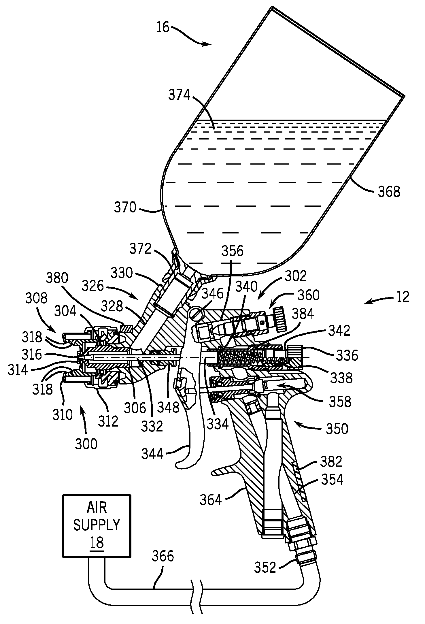
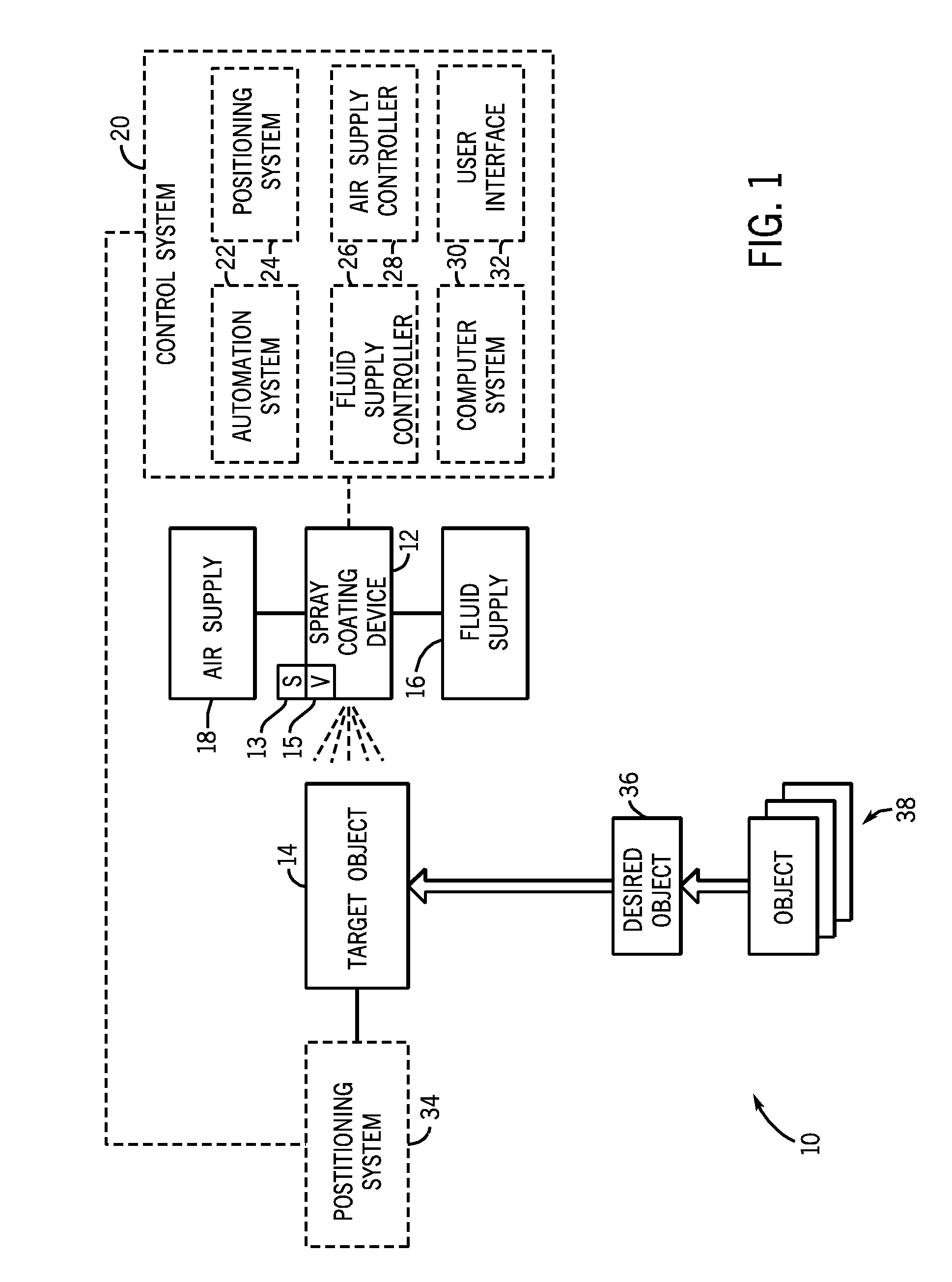
[0010]FIG. 1 is a flow chart illustrating an exemplary spray coating system 10, which includes a spray coating gun 12 for applying a desired coating to...


PUM

PropertyMeasurementUnit
distanceaaaaaaaaaa
flow rateaaaaaaaaaa
velocityaaaaaaaaaa

Abstract

A spray gun, in one embodiment, is provided with a sensor configured to monitor distance between the spray gun and a target object, and a drive responsive to the sensor, wherein the drive is configured to control a fluid valve of the spray gun based on the distance. A retrofit kit, in another embodiment, is provided with a feedback-controlled system configured to change fluid flow of a spray gun in response to one or more sensed parameters indicative of condition of a target object, a relationship between the spray gun and the target object, or a combination thereof. A spray controller, in a further embodiment, is provided with a control configured to terminate or decrease fluid flow of a spray in response to a first spray stroke away from a target object, and configured to start, continue, or increase fluid flow of the spray in response to a second spray stroke toward the target object. In yet another embodiment, a method of operation is provided for controlling fluid flow in response to feedback associated with a target object. In addition, a tangible medium is provided with instructions stored on the tangible medium, wherein the instructions comprise code configured to terminate or decrease fluid flow of a spray if the spray is not directed toward a target object, and code configured to start, continue, or increase fluid flow of the spray if the spray is directed toward the target object.

Description

FIELD OF THE INVENTION[0001]The invention relates generally to spray devices and, more particularly, to the transfer efficiency of spray guns.BACKGROUND[0002]This section is intended to introduce the reader to various aspects of art that may be related to various aspects of the present invention, which are described and / or claimed below. This discussion is believed to be helpful in providing the reader with background information to facilitate a better understanding of the various aspects of the present invention. Accordingly, it should be understood that these statements are to be read in this light, and not as admissions of prior art.[0003]The objective when spraying paint is to maximize the amount of coating material that is deposited on the substrate and minimize the amount that goes into the atmosphere. High volume low pressure (HVLP) and high transfer efficiency (HTE) spray guns have been designed and mandated in many jurisdictions to limit the amount of overspray due to the p...

Claims


Application Information

Patent Timeline
Patent Type & Authority Applications(United States)
IPC IPC(8): B05B17/04B05B17/00B05B15/00B05B7/12B05D1/02B05C11/00
CPCB05B7/0815B05B7/1209B05B12/124B05B7/2478B05B12/122B05B7/1218
Inventor CHARPIE, MARK E.
Owner ILLINOIS TOOL WORKS INC
Why Eureka
Try Eureka