Superjunction device having a dielectric termination and methods for manufacturing the device

a dielectric termination and superjunction technology, applied in the direction of solid-state devices, electric devices, basic electric elements, etc., can solve the problems of termination designs consuming a certain semiconductor area, poor yield, and higher on-state voltage, and achieve the effect of preventing voltage breakdown

Inactive Publication Date: 2009-07-16
ICEMOS TECH
View PDF38 Cites 24 Cited by
  • Summary
  • Abstract
  • Description
  • Claims
  • Application Information

AI Technical Summary

Benefits of technology

[0010]Still another preferred embodiment of the present invention comprises a method of preventing voltage breakdown at a surface of a semiconductor substrate of a superjunction semiconductor device. The method includes placing, proximate an edge portion of the semiconductor substrate, a termination structure having a layer of dielectric of an effective thickness. The termination structure consumes about 0% of the surface area of the surface of the semiconductor substrate.

Problems solved by technology

This results in a poorer yield and a higher on-state voltage.
Prior art superjunction device edge termination designs consume a certain semiconductor area to realize the high breakdown voltage.

Method used


Image

  • Superjunction device having a dielectric termination and methods for manufacturing the device
  • Superjunction device having a dielectric termination and methods for manufacturing the device
  • Superjunction device having a dielectric termination and methods for manufacturing the device

Examples


Embodiment Construction

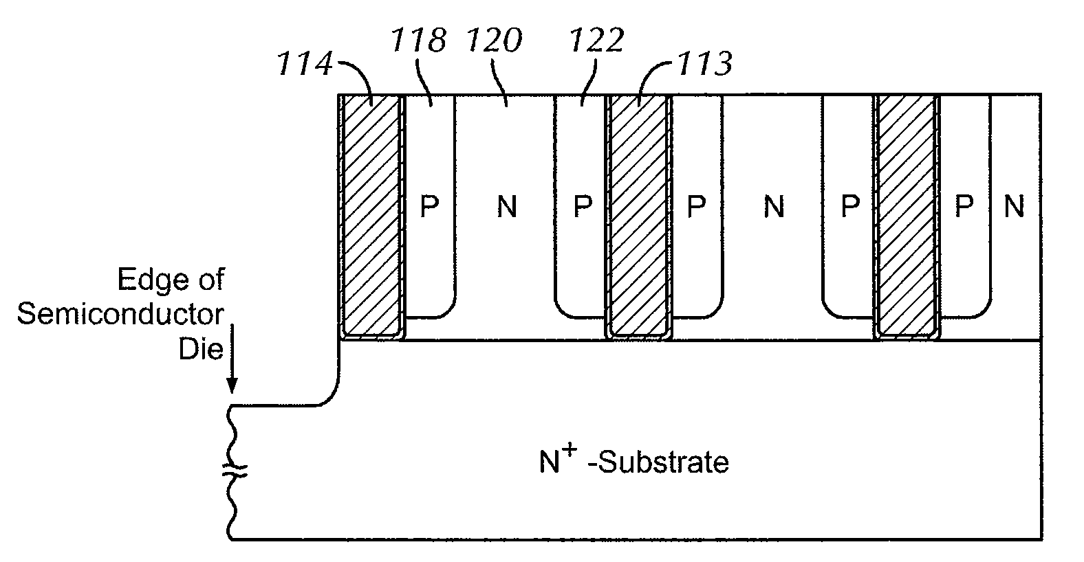
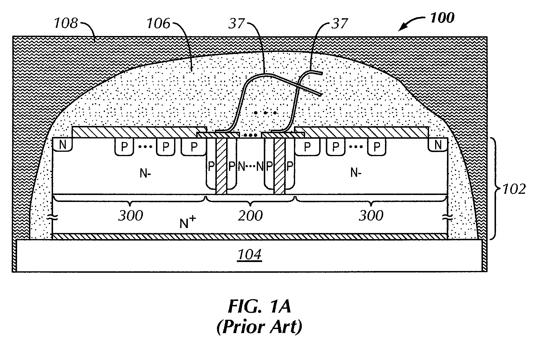
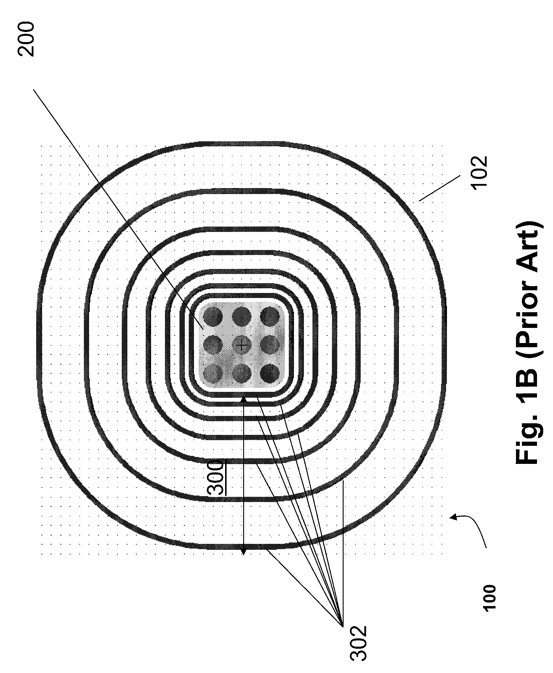
[0064]Certain terminology is used in the following description for convenience only and is not limiting. The words “right”, “left”, “lower”, and “upper” designate directions in the drawing to which reference is made. The words “inwardly” and “outwardly” refer direction toward and away from, respectively, the geometric center of the object described and designated parts thereof. The terminology includes the words above specifically mentioned, derivatives thereof and words of similar import. Additionally, it must be noted that as used herein and in the appended claims, the singular forms “a,”“an,” and “the” include plural reference unless the context clearly dictates otherwise.

[0065]Although any embodiment of the present invention may refer to a particular conductivity (e.g., p-type or n-type), it will be readily understood by those skilled in the art that p-type conductivity can be switched with n-type conductivity and vice versa and the device will still be functionally correct (i.e...


PUM


Abstract

A superjunction semiconductor device is provided having at least one column of a first conductivity type and at least one column of a second conductivity type extending from a first main surface of a semiconductor substrate toward a second main surface of the semiconductor substrate opposed to the first main surface. The at least one column of the second conductivity type has a first sidewall surface proximate the at least one column of the first conductivity type and a second sidewall surface opposed to the first sidewall surface. A termination structure is proximate the second sidewall surface of the at least one column of the second conductivity type. The termination structure includes a layer of dielectric of an effective thickness and consumes about 0% of the surface area of the first main surface. Methods for manufacturing superjunction semiconductor devices and for preventing surface breakdown are also provided.

Description

CROSS-REFERENCE TO RELATED APPLICATIONS[0001]This application claims the benefit of U.S. Provisional Patent Application No. 61 / 020,540, filed on Jan. 11, 2008, entitled “Superjunction Semiconductor Device Having A Dielectric Termination And Methods for Manufacturing The Device,” the entire contents of which are incorporated by reference herein.BACKGROUND OF THE INVENTION[0002]Embodiments of the present invention relate to a superjunction semiconductor device and a method for manufacturing the superjunction semiconductor device. In particular, embodiments of the present invention relate to a superjunction device having a voltage termination structure having a layer of dielectric of an effective thickness.[0003]The success of a controllable semiconductor device at high or ultra-high voltages is almost entirely determined by a successful implementation of the edge termination. Due to the termination of periodic cell structures at the edges of semiconductor devices, high electric fields...

Claims


Application Information

Patent Timeline
Patent Type & Authority Applications(United States)
IPC IPC(8): H01L29/06H01L21/30H01L21/762
CPCH01L29/0634H01L29/0649H01L2924/1305H01L2924/12032H01L2924/13055H01L2924/1301H01L21/0217H01L21/02167H01L21/02123H01L21/02118H01L2924/13091H01L29/0653H01L29/0661H01L29/1095H01L29/407H01L29/66143H01L29/7811H01L29/861H01L29/872H01L2224/4847H01L2224/73265H01L2924/00H01L2224/8592H01L2924/10155H01L2924/10156
Inventor CHENG, XU
Owner ICEMOS TECH
Why Eureka
Try Eureka