
Pyrotechnic cup

a technology of pyrotechnic cups and cups, which is applied in the direction of electric fuzes, pedestrian/occupant safety arrangements, vehicular safety arrangements, etc., can solve the problems of cup fragmentation, change of inflator, and deployment of inflators, so as to prevent the fragmentation of the cup, and prevent the effect of the cup fragmentation

Inactive Publication Date: 2009-07-16
AUTOLIV ASP INC
View PDF28 Cites 18 Cited by
  • Summary
  • Abstract
  • Description
  • Claims
  • Application Information

AI Technical Summary

Benefits of technology

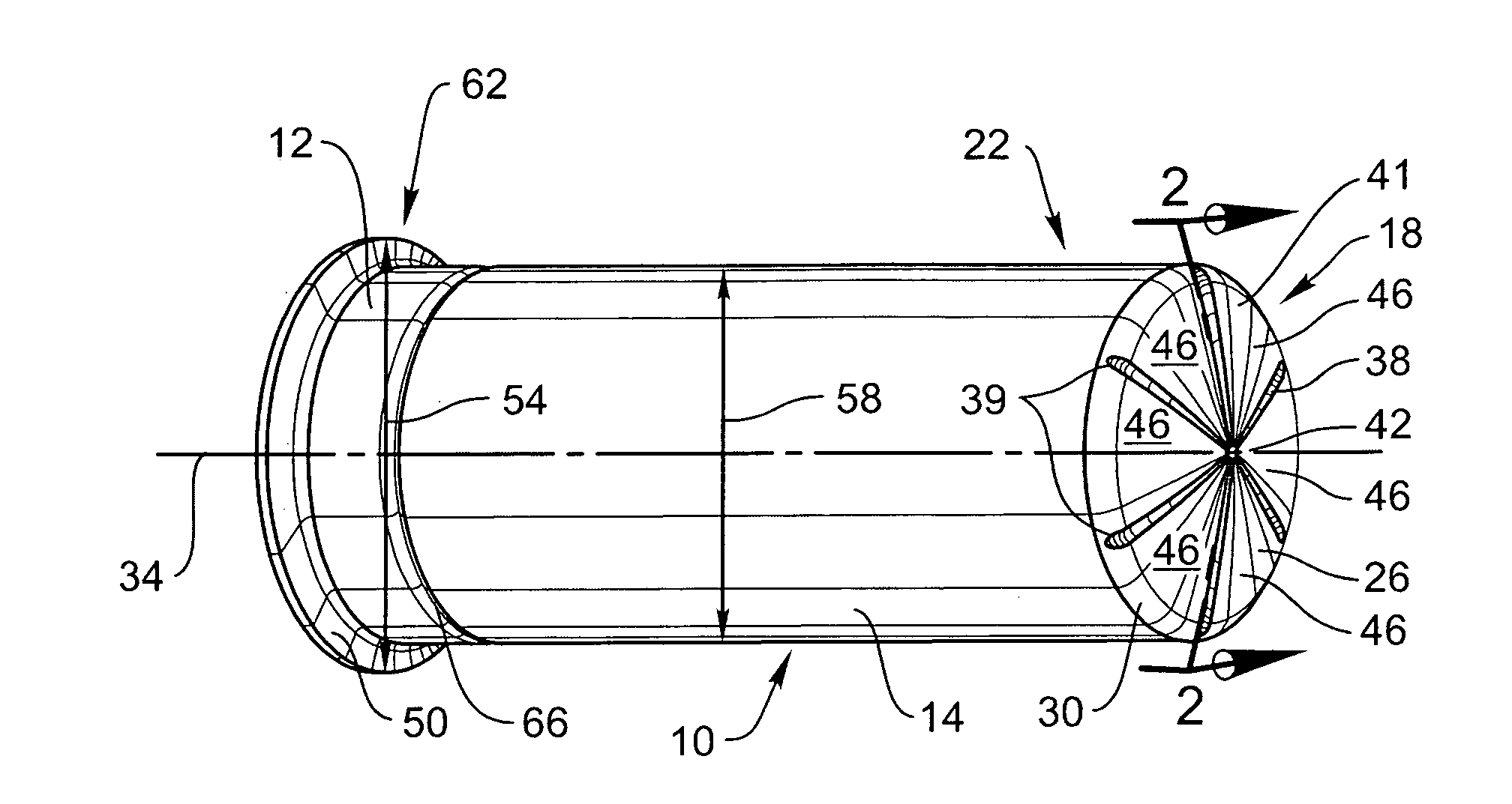
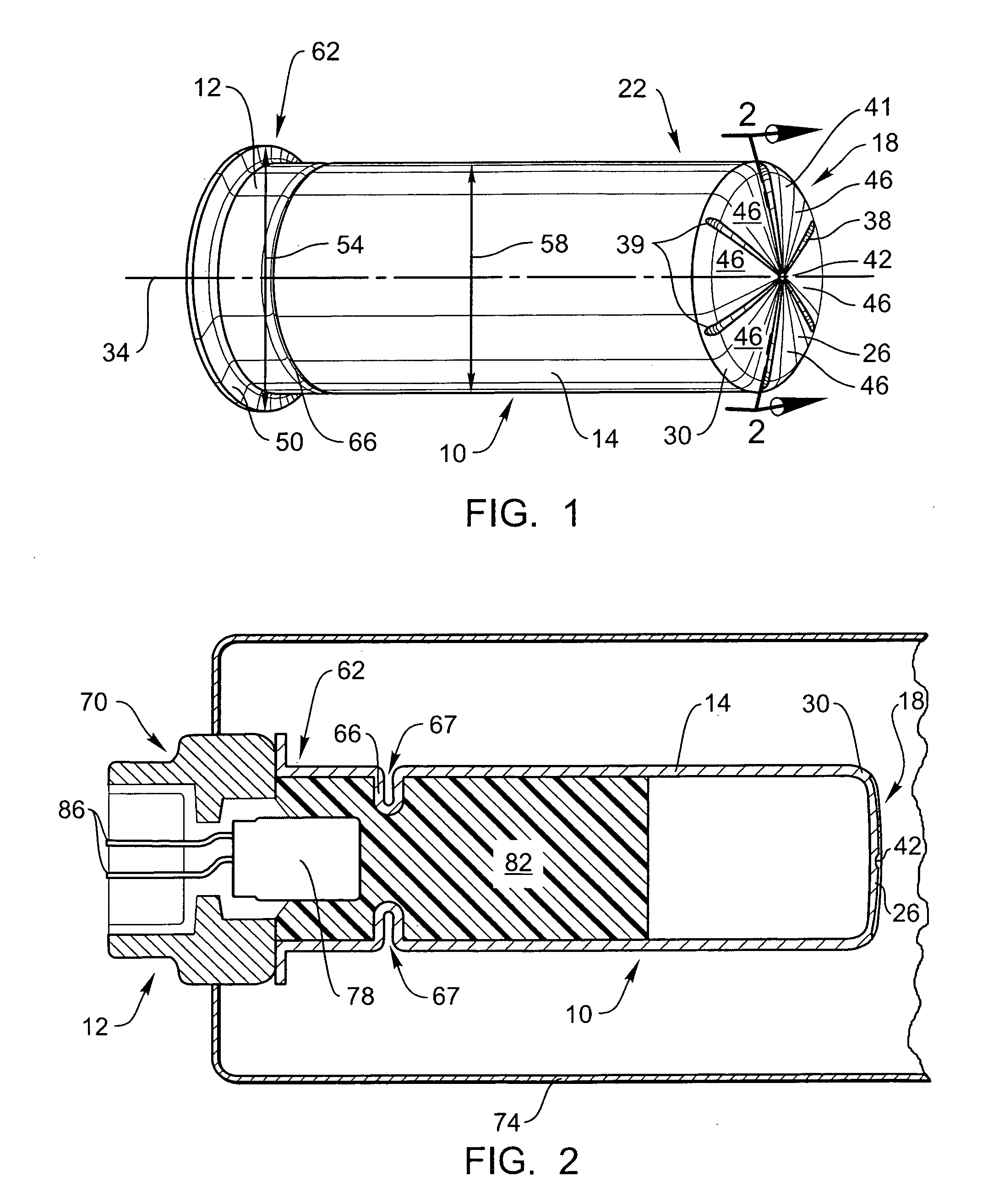
[0011]The present embodiments also relate to a method for preventing fragmentation of a pyrotechnic cup in an inflator. The method may include the step of obtaining a pyrotechnic cup. This pyrotechnic cup comprises a cylindrical portion, a dome attached to a first end of the cylindrical portion, and a cruciform positioned at the apex of the dome. The method also includes the step of positioning the cup around a squib and a combustible material. Once positioned, the dome prevents fragmentation of the cup.
[0013]The pyrotechnic cup may include a cylindrical portion and a dome. The dome may be positioned at an end of the cylindrical portion. The dome may also have an apex. The dome may further comprise a top piece and a tapered portion. The tapered portion is connected to the cylindrical portion. The tapered portion may be curved and may create a smooth transition from the top piece to the cylindrical portion.
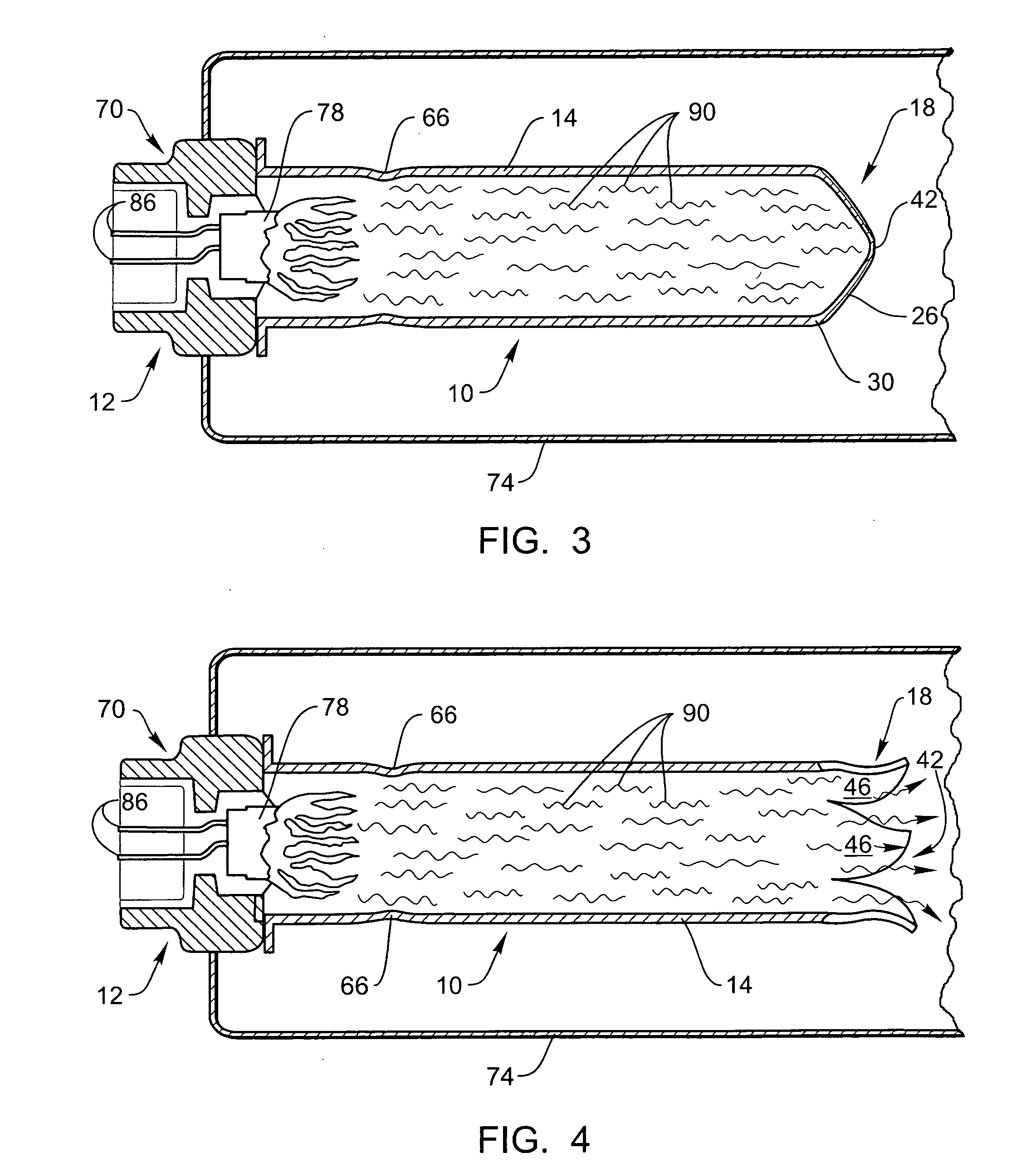
[0018]The formation of the gas in the cup increases the pressure within the cup. In turn, the increase in pressure in the cup causes the crimped bend to expand. More specifically, the formation of the gas pushes against the cup and causes the crimped bend to unfold and expand, thereby increasing the length of the pyrotechnic cup.

Problems solved by technology

Such ignition of the combustible material, in turn, creates a pressure change in the inflator and results in deployment of the inflator.
Unfortunately, during ignition / combustion of the combustible material, the pressure change caused by combustion often causes the cup to fragment into small pieces.
Obviously, it is undesirable to have fragments of the cup enter the airbag; accordingly, the inflator must be designed to ensure that these fragments are retained within the inflator and not allowed to enter the airbag.
Unfortunately, these charge holders and / or cup retention devices increase the cost of the inflator.

Method used


Image

  • Pyrotechnic cup
  • Pyrotechnic cup
  • Pyrotechnic cup

Examples


Embodiment Construction

[0032]The presently preferred embodiments of the present invention will be best understood by reference to the drawings, wherein like parts are designated by like numerals throughout. It will be readily understood that the components of the present invention, as generally described and illustrated in the figures herein, could be arranged and designed in a wide variety of different configurations. Thus, the following more detailed description of the embodiments of the present invention, as represented in the Figures, is not intended to limit the scope of the invention, as claimed, but is merely representative of presently preferred embodiments of the invention.

[0033]Referring now to FIG. 1, a perspective view of an embodiment of a pyrotechnic cup 10 is illustrated. This pyrotechnic cup 10 is designed for use with an airbag inflator (not shown in FIG. 1). More specifically, the pyrotechnic cup 10 may be used as part of an initiator assembly 12 that operates to deploy an inflator durin...


PUM


Abstract

A new type of pyrotechnic cup is disclosed. The pyrotechnic cup is designed such that it may be used as part of an airbag initiator. In some embodiments, the cup comprises a cylindrical portion and a dome that is attached to a first end of the cylindrical portion. A cruciform is also added to the cup. The cruciform is positioned at the apex of the dome. In some embodiments, the cruciform comprises one or more petals. Other embodiments may be designed in which deployment of the initiator causes gas to be directed out of the pyrotechnic cup via the apex of the dome.

Description

BACKGROUND OF THE INVENTION[0001]Airbags and airbag systems have been implemented and used on motor vehicles for many years as a safety device. These systems are designed such that, in the event of a crash or accident, an airbag will be inflated and positioned adjacent the vehicle occupant. Such positioning of the airbag prevents the vehicle occupant from harmful impact with the steering wheel, the dashboard, or other portions of the vehicle interior. Because airbag systems have been credited with saving many lives, the inclusion of airbag systems on new vehicles is now a requirement in many countries.[0002]In order to deploy the airbag, the airbag system will generally include an inflator. An inflator is a device that is capable of rapidly producing / channeling large quantities of inflation gas into the airbag during deployment. This influx of gas into the airbag inflates the airbag and causes the airbag to become positioned on the vehicle interior.[0003]In order to rapidly deploy t...

Claims


Application Information

Patent Timeline
IPC IPC(8): B60R21/26
CPCB60R21/26F42B3/04B60R2021/26029B60R21/264
Inventor BRISIGHELLA, JR., DARIO G.AYERS, MIKE
Owner AUTOLIV ASP INC
Learn More