
Structural material of diamond like carbon composite layers and method of manufacturing the same

a technology of diamond like carbon and composite layers, which is applied in the direction of superimposed coating process, natural mineral layered products, instruments, etc., can solve the problems of reduced adhesion extreme limitations in application of dlc thin films, and generation of residual stress. , to achieve the effect of improving adhesion

Active Publication Date: 2009-07-02
IND TECH RES INST
View PDF4 Cites 26 Cited by
  • Summary
  • Abstract
  • Description
  • Claims
  • Application Information

AI Technical Summary

Benefits of technology

[0010]Accordingly, the present invention is directed to a structural material of DLC composite layers, capable of significantly improving the adhesion between the DLC thin film and a substrate.
[0011]The present invention is further directed to a method of manufacturing a structural material of DLC composite layers, capable of improving a ratio of the sp3 diamond structure of the DLC thin film, so as to avoid the fragmentation of the structural material of DLC composite layers.

Problems solved by technology

Although the DLC thin films have excellent properties, during film coating, the surface of the film layer is bombed by coating particles continuously, and thus residual stress is generated inevitably during coating the DLC thin films.
Accordingly, excessively high residual stress will cause cracks in the layers, thus decreasing the adhesion of the DLC thin films.
Further, due to the sensitivity of the DLC thin film to environment and the low adhesion caused by the diffusion of interface stress between the DLC thin film and a substrate, the application of the DLC thin film is limited extremely.
However, during coating the DLC thin film, when the ratio of sp3 diamond structure of the manufactured DLC thin film is improved higher, the internal stress of the film is easily increased, thus fragmentation automatically occurs.
Additionally, during coating the DLC thin film and compositing with another substrate, due to the high-ratio diamond structure of the film and the poor adhesion between the film and the substrate, film removal likely occurs.

Method used


Image

  • Structural material of diamond like carbon composite layers and method of manufacturing the same
  • Structural material of diamond like carbon composite layers and method of manufacturing the same
  • Structural material of diamond like carbon composite layers and method of manufacturing the same

Examples


first embodiment

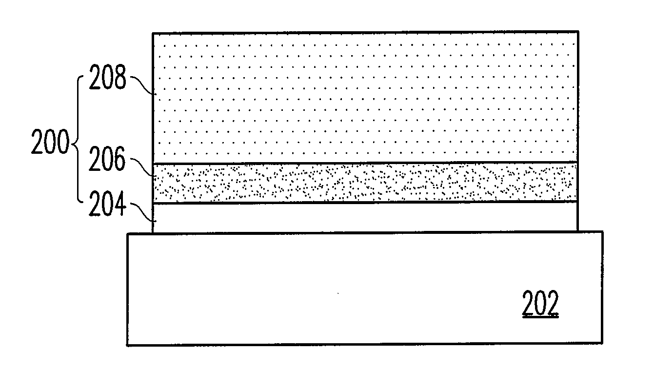
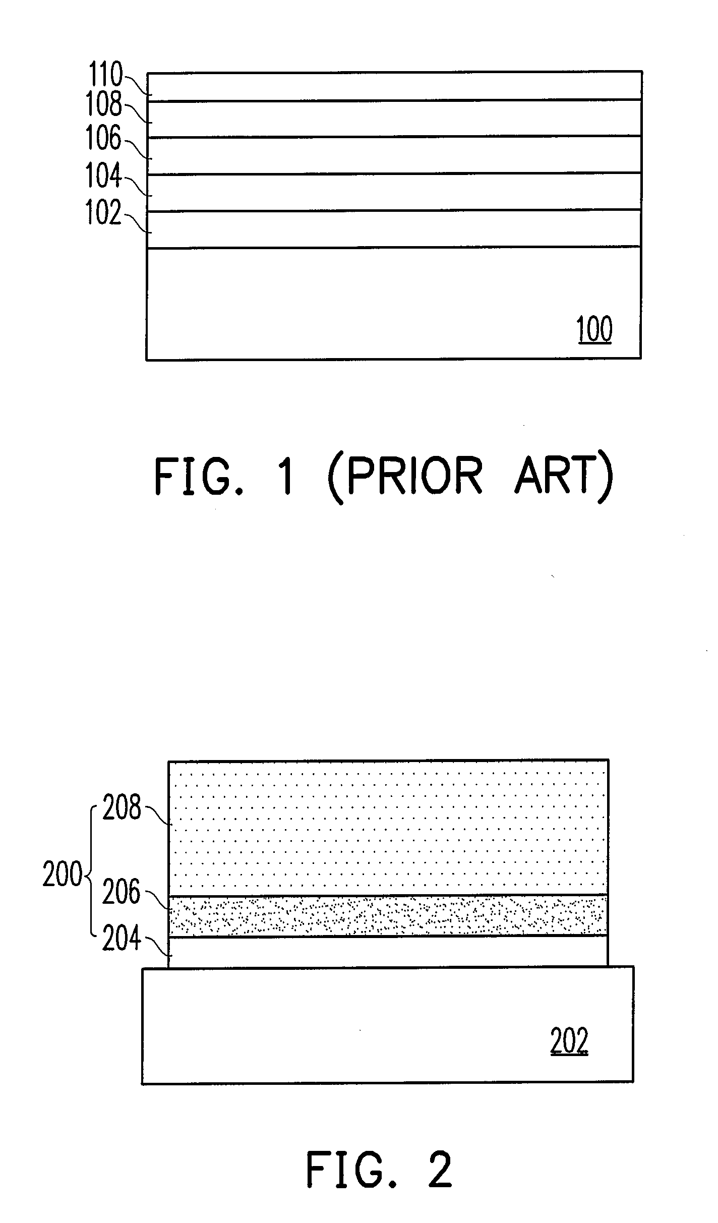
[0035]FIG. 2 is a schematic cross-sectional view of a structural material of DLC composite layers according to the present invention.

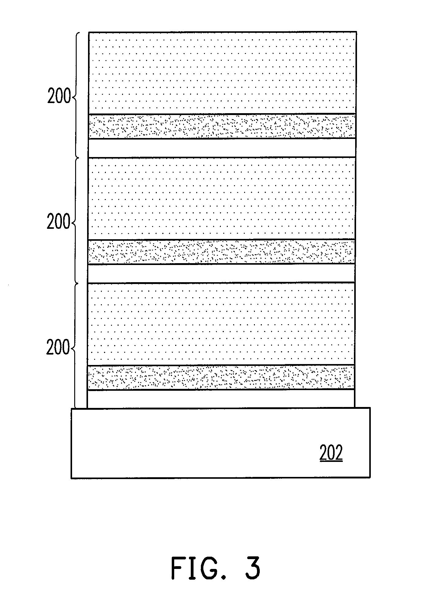
[0036]Referring to FIG. 2, the structural material of DLC composite layers of the first embodiment includes a single layer of composite material 200. The composite material 200 can be formed on a substrate 202. The substrate 202 can be a metal substrate or a non-metal substrate. The composite material 200 is consisted of a metal layer 204, a first metal nitride layer 206, and a DLC thin film 208. The metal layer 204 includes aluminum (Al), copper (Cu), zirconium (Zr), nickel (Ni), or vanadium (V). The first metal nitride layer 206 includes aluminum nitride (Al—N), zirconium nitride (Zr—N), vanadium nitride (V—N), or nickel nitride (Ni—N). In the first embodiment, the DLC thin film 208 in the composite material 200 includes pure carbon or a tetragonally bonded amorphous carbon (ta-C) structure containing less than 10% of hydrogen atom, nitrogen atom, or...

second embodiment

[0039]FIG. 5 is a flow chart of process of a method of manufacturing a structural material of DLC composite layers according to the present invention.

[0040]Referring to FIG. 5, the manufacturing method of the second embodiment is performed by using graphite and a metal target material through a physical vapour deposition. The physical vapour deposition can be vacuum sputtering, pulsed laser deposition or arc ion evaporation. For example, in a vacuum chamber, a target material is dissociated through the arc ion evaporation, and an appropriate negative bias is applied onto the substrate, so as to introduce the atoms or ions dissociated from the target material to the substrate to be deposited, and at the same time, an inert gas is charged as a reacting gas. First, in Step 50, a metal layer is prepared on a substrate, and the metal layer includes aluminum (Al), copper (Cu), zirconium (Zr), nickel (Ni), or vanadium (V). Next, in Step 502, a first metal nitride layer is prepared on the m...

third embodiment

[0043]FIG. 9 is a schematic cross-sectional view of a structural material of DLC composite layers according to the present invention.

[0044]Referring to FIG. 9, the structural material of DLC composite layers of the third embodiment includes a single layer of composite material 900. The composite material 900 can be formed on a substrate 902. The substrate 902 can be a non-metal substrate. The composite material 900 is consisted of a metal nitride layer 904 and a DLC thin film 906. The metal nitride layer 904 includes aluminum nitride (Al—N), zirconium nitride (Zr—N), vanadium nitride (V—N), or nickel nitride (Ni—N). In the third embodiment, the DLC thin film 906 in the composite material 900 includes pure carbon or a tetragonally bonded amorphous carbon (ta-C) structure containing less than 10% of hydrogen atom, nitrogen atom, or metal atom. Further, a thickness of the metal nitride layer 904 in the composite material 900 is, for example, 20 nm-100 nm. A thickness of the DLC thin fi...


PUM

PropertyMeasurementUnit
thicknessesaaaaaaaaaa
temperatureaaaaaaaaaa

Abstract

A structural material of diamond like carbon (DLC) composite layers is provided. The structural material includes a composite material which is consisted of a metal layer, a first metal nitride layer, and a DLC thin film. The metal layer includes aluminum (Al), copper (Cu), zirconium (Zr), nickel (Ni), or vanadium (V). The first metal nitride layer includes aluminum nitride (Al—N), zirconium nitride (Zr—N), vanadium nitride (V—N), or nickel nitride (Ni—N). The DLC thin film of the structural material of DLC composite layers has high quality tetragonally bonded amorphous carbon (ta-C) with a sp3(C—C) bonding ratio of more than 30%. Therefore, it is suitable for the work pieces in the mechanical, chemical, electricity, photoelectric, and heat transfer fields.

Description

CROSS-REFERENCE TO RELATED APPLICATION[0001]This application claims the priority benefit of Taiwan application serial no. 96151043, filed on Dec. 28, 2007. The entirety the above-mentioned patent application is hereby incorporated by reference herein and made a part of specification.BACKGROUND OF THE INVENTION[0002]1. Field of the Invention[0003]The present invention generally relates to a structural material of diamond like carbon (DLC) composite layers and a method of manufacturing the same.[0004]2. Description of Related Art[0005]Diamond like carbon (DLC) thin films have attracted considerable attentions in the last decade, mainly because the DLC thin films have high hardness, high Young's modulus, high abrasive resistance, high thermal conductivity, low friction coefficient, and chemical inertness. By means of property adjustment through such a surface modification, the DLC thin films are applied to various precision work pieces and elements to improve and promote the mechanical...

Claims


Application Information

Patent Timeline
Patent Type & Authority Applications(United States)
IPC IPC(8): B32B9/00C23C14/32C23C14/00
CPCC22C1/002C23C14/024C23C14/0605C23C28/322Y10T428/30C23C28/343Y10T428/24975Y10T428/265C23C28/34Y10T428/31678C22C1/11
Inventor LEU, MING-SHENGWU, JIN-BAOCHANG, JIA-JEN
Owner IND TECH RES INST
Learn More