
Magnetic Resolver

a resolver and magnetic technology, applied in the field of magnetic resolvers, can solve the problems of reducing becoming unnecessary to wind wires. , to achieve the effect of enhancing the resolution and accuracy of detecting a rotation angle, easy assembly and increasing the number of windings of the coils

Active Publication Date: 2009-07-16
TOYOTA JIDOSHA KK +1
View PDF3 Cites 23 Cited by
  • Summary
  • Abstract
  • Description
  • Claims
  • Application Information

AI Technical Summary

Benefits of technology

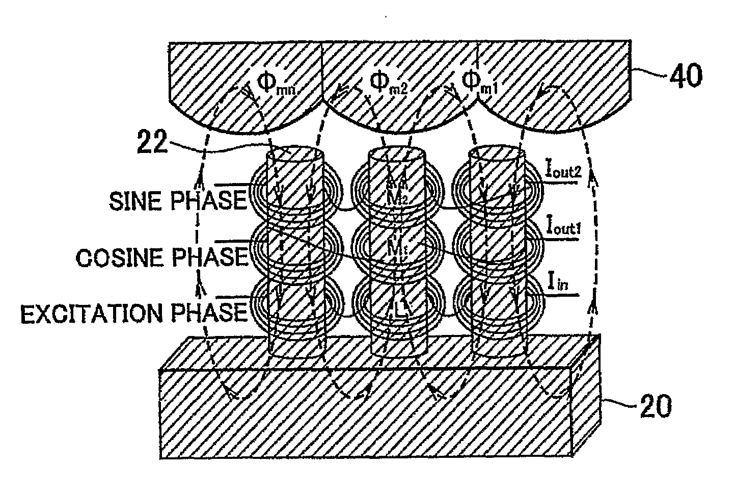
[0008]An object of the present invention is to provide a magnetic resolver that is easily assembled, and in which the number of windings of the coils can be increased without significantly increasing the thickness of the resolver. Another object of the present invention is to provide a magnetic resolver that enhances the resolution and accuracy of detecting a rotation angle.

Problems solved by technology

In addition, it becomes unnecessary to wind wire to obtain coils.
However, Japanese Utility Model Application Publication No. 5-3921 fails to disclose a specific configuration of a substrate on which the film-shaped coils are formed.
If the substrates of the film-shaped coils are individually provided for the respective protruding poles, assembly is difficult.
In addition, when the film-shaped coils are used, it is more difficult to easily increase the number of windings of the coil, as compared to a conventional resolver in which wire is wound around the cores on a stator that are faced toward a rotor in the radial direction.
Accordingly, there is a lack of information to efficiently enhance the resolution and accuracy of detecting the rotation angle.

Method used


Image

  • Magnetic Resolver
  • Magnetic Resolver
  • Magnetic Resolver

Examples


first embodiment

[0066]In the first embodiment, the function Y is represented as follows:

Y=a {sin N(θ−90° / N)+1}

wherein N is the angular multiplication factor, and r (mm) is the radius of the core 22 as described above and a is the amplitude. The amplitude a may be equal to the radius r of the core 22. In this case, as apparent from this equation, the position of the point on the profile line of the rotor plate 40 on the reference axis varies according to the sine curve of which the amplitude is r as the rotation angle θ varies. Thus, the range of variation 2 r of the profile line of the rotor plate 40 in the radial direction is equal to the diameter 2 r of the core 22. When the resolver is of 7×, that is, N=7, and r=4 [m], for example, the function Y is represented as follows:

Y=4{sin 7(θ−90° / 7)+1}

[0067]For the sake of convenience in explanation, an example in which the amplitude a is equal to the radius r will be described below. The region of the rotor plate 40 between the maximum radius and the mi...

second embodiment

[0082]With regard to the second embodiment, the function Y is represented as follows:

Y=A·r {sin N(θ−90° / N)+1}

wherein A is a coefficient, and is preferably set within the range of 0.8 to 0.9 as described later. As apparent from this equation, as the rotation angle θ varies, the position of the point on the profile line of the rotor plate 40 on the reference axis varies according to the sine curve of which the amplitude is A·r that is slightly smaller than the radius r of the core 22. Specifically, the range of variation 2 A·r of the profile line of the rotor plate 40 in the radial direction is set smaller than the diameter 2 r of the core 22. When the resolver is of 7×, that is, N=7, and r=4 [m], for example, the function Y is represented as follows:

Y=4A{sin 7(θ−90° / 7)+1}

[0083]For the sake of convenience in explanation, the region of the rotor plate 40 between the maximum radius and the minimum radius thereof (the region of which the width in the radial direction is 2 A·r) is referre...


PUM


Abstract

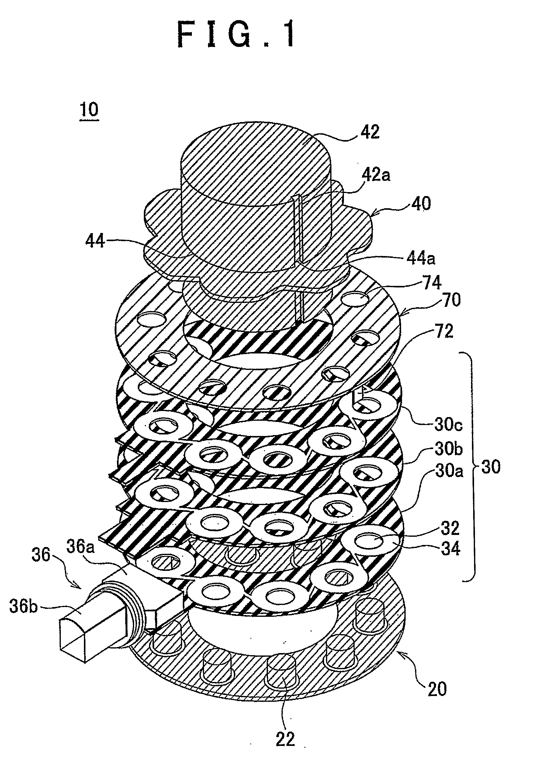
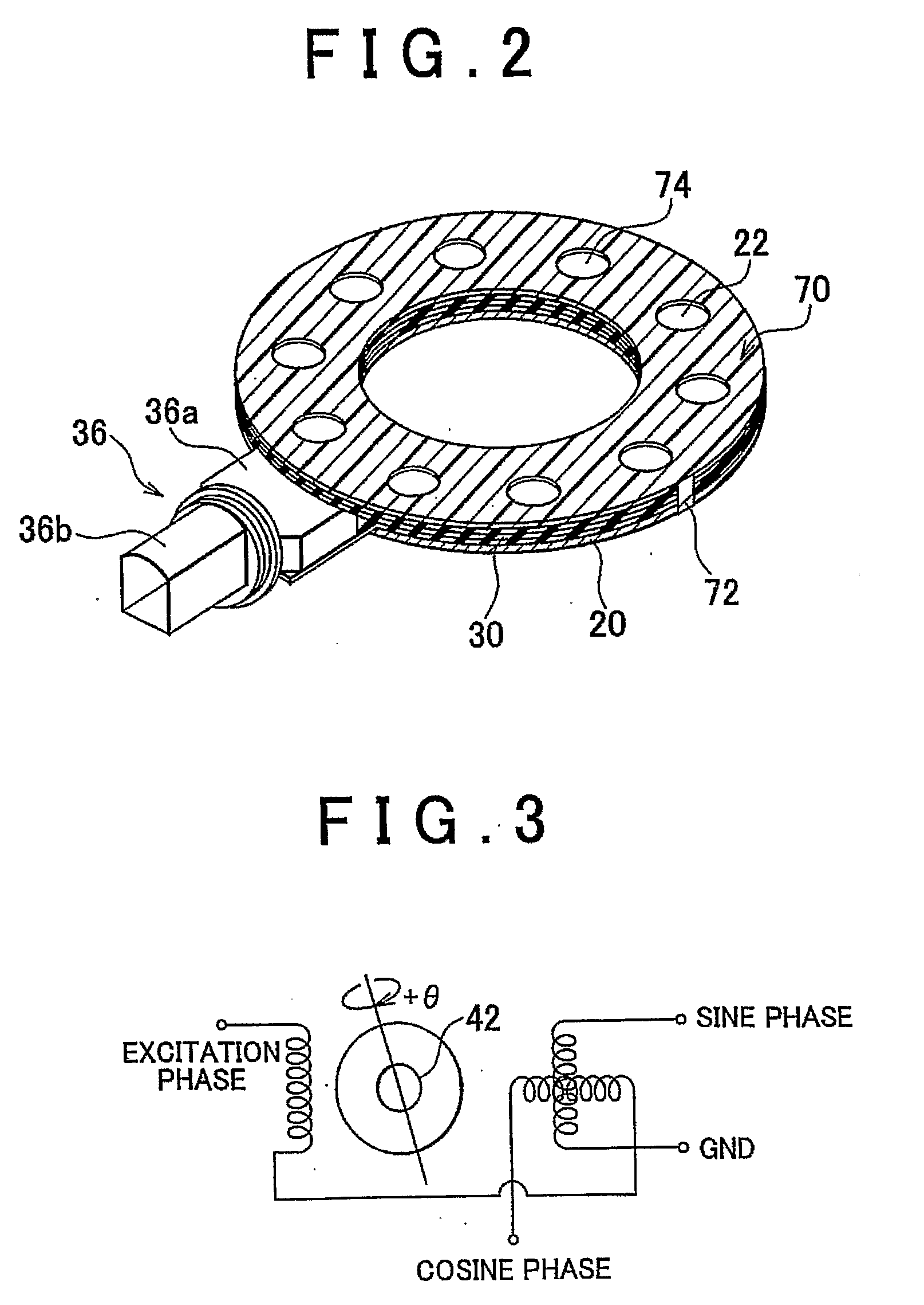
A magnetic resolver includes: a plurality of columnar cores disposed on an annular plate; a coil portion disposed around each of the columnar cores; and an annular rotor having a sinusoidal profile that rotates in a plane parallel to the top faces of the columnar cores around a rotation axis that passes through the center of the annular plate. The coil portion may be formed of a patterned coil formed on an annular substrate that has a plurality of through holes made therein through which the plurality of cores are passed, the patterned coil being formed around the through hole.

Description

BACKGROUND OF THE INVENTION[0001]1. Field of the Invention[0002]The present invention relates to a magnetic resolver for detecting the rotation angle of a rotor.[0003]2. Description of the Related Art[0004]Conventional magnetic resolvers generally include a rotatable rotor core, a stator core, with two stator plates that sandwich the rotor core from above and below and that have convex, protruding poles arranged along the circumference of the stator core, and thin-film coils that are wound around the respective protruding poles of the stator core, and that detects a rotation angle of the rotor core by using the fact that the inductance of a coil varies with the rotation angle of the rotor core (see, Japanese Utility Model Application Publication No. 5-3921 (“JP-5-3921”), for example).[0005]In a conventional resolver as described above, in which the film-shaped coils are used that are formed on a substrate in a pattern, it is possible to realize a thinner resolver body as compared to...

Claims


Application Information

Patent Timeline
Patent Type & Authority Applications(United States)
IPC IPC(8): H02K24/00G01D5/22
CPCH02K24/00G01D5/2046
Inventor NISHIGUCHI, MASAYUKISEKITOMI, YUJIHAMAMOTO, YOJI
Owner TOYOTA JIDOSHA KK
Learn More