

Display device and luminance control method therefor
a technology of luminance control and display device, which is applied in the direction of static indicating devices, television systems, instruments, etc., can solve the problems of interference with the entrance of extraneous light into extraneous light, poor appearance of display screen, and mounting error of liquid crystal display panel, etc., to achieve the effect of easily and accurately performing luminance control
- Summary
- Abstract
- Description
- Claims
- Application Information
AI Technical Summary
Benefits of technology
Problems solved by technology
Method used
Image

Examples
first preferred embodiment
(1) Constitution of the First Preferred Embodiment
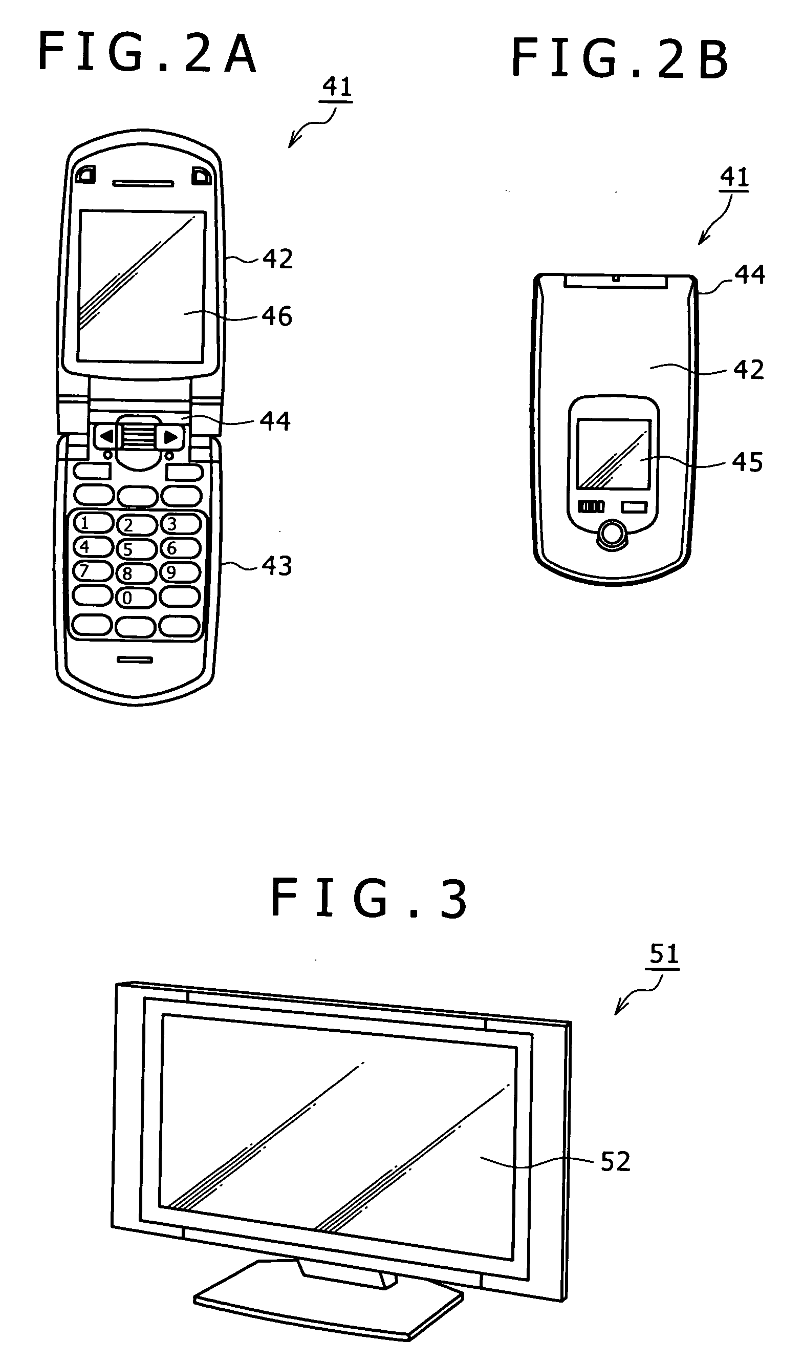
[0047]FIGS. 2A and 2B are plan views of a mobile phone 41 as a display device according to the first preferred embodiment of the present invention. FIG. 2A shows an open condition of the mobile phone 41, and FIG. 2B shows a folded condition of the mobile phone 41. The mobile phone 41 is composed of an upper body portion 42, a lower body portion 43, and a connecting portion 44 for connecting the upper body portion 42 and the lower body portion 43 so that the upper body portion 42 is foldable with respect to the lower body portion 43. As shown in FIG. 2B, the upper body portion 42 of the mobile phone 41 is provided with an auxiliary display portion 45 capable of indicating various kinds of information to a user in the folded condition of the mobile phone 41. Further, as shown in FIG. 2A, the upper body portion 42 is provided with a main display portion 46 capable of indicating various kinds of information to the user in the open condit...
second preferred embodiment
[0070]In contrast to FIGS. 7A and 7B and FIGS. 19A and 19B, FIGS. 8A and 8B show a liquid crystal display panel 76 applied to a display device according to a second preferred embodiment of the present invention. The display device according to the second preferred embodiment includes the liquid crystal display panel 76 in place of the liquid crystal display panel 71 shown in FIGS. 7A and 7B.
[0071]The liquid crystal display panel 76 according to the second preferred embodiment has the same configuration as that of the liquid crystal display panel 71 according to the first preferred embodiment except that a correcting sensor 8A is provided in the light shielding area 3 and that the output signal from the extraneous light sensor 8 is corrected by the output signal from the correcting sensor 8A prior to the luminance controlling step. The configuration of the correcting sensor 8A and the configuration of a sensor circuit 24 for processing the output signal from the correcting sensor 8A ...
third preferred embodiment
[0073]In contrast to FIGS. 8A and 8B, FIGS. 9A and 9B show a liquid crystal display panel 81 applied to a display device according to a third preferred embodiment of the present invention. The display device according to the third preferred embodiment includes the liquid crystal display panel 81 in place of the liquid crystal display panel 71 shown in FIGS. 7A and 7B.
[0074]In the liquid crystal display panel 81, the correcting sensor 8A is located in the light shielding area 3 at a position close to the effective pixel area 2, and the light shielding member 15B shown in FIG. 8B is omitted to allow the correcting sensor 8A to detect extraneous light. Further, a part of the light shielding film 11 corresponding to the position of the correcting sensor 8A is replaced by a filter 82 capable of selectively transmitting a wavelength band of infrared radiation. That is, the correcting sensor 8A in the liquid crystal display panel 81 detects merely the wavelength band of infrared radiation ...
PUM
 Abstract
Description
Claims
Application Information