Heat-dissipating module having a dust removing mechanism, and assembly of an electronic device and the heat-dissipating module

a technology of heat dissipation module and dust removal mechanism, which is applied in the direction of lighting and heating apparatus, instruments, and semiconductor/solid-state device details, etc. it can solve the problems of affecting the operation the damage of the electronic device due to poor heat dissipation or dust accumulation of the relative difficulty of the user cleaning the heat dissipation module b>1

Inactive Publication Date: 2009-07-16
WISTRON CORP
View PDF7 Cites 16 Cited by
  • Summary
  • Abstract
  • Description
  • Claims
  • Application Information

AI Technical Summary

Benefits of technology

[0014]In the present invention, with the provision of the dust removing mechanism, the heat-dissipating fin base may be constantly maintained in a clean and ventilated state, and will not become poorly ventilated after a period of use due to dust accumulation and blocking, which may affect heat dissipation. At the same time, possible damage to the electronic device due to poor heat dissipation or dust accumulation of the heat-dissipating module may be prevented.

Problems solved by technology

However, one problem commonly associated with the conventional heat-dissipating module 1 is that dust will accumulate in clearances among adjacent pairs of the heat-dissipating fins 12 after a period of use.
However, since the heat-dissipating module 1 is mounted within the housing, it is relatively difficult for the user to clean the heat-dissipating module 1.
In addition, the electronic device is liable to be damaged due to high heat or severe dust accumulation.

Method used


Image

  • Heat-dissipating module having a dust removing mechanism, and assembly of an electronic device and the heat-dissipating module
  • Heat-dissipating module having a dust removing mechanism, and assembly of an electronic device and the heat-dissipating module
  • Heat-dissipating module having a dust removing mechanism, and assembly of an electronic device and the heat-dissipating module

Examples


Embodiment Construction

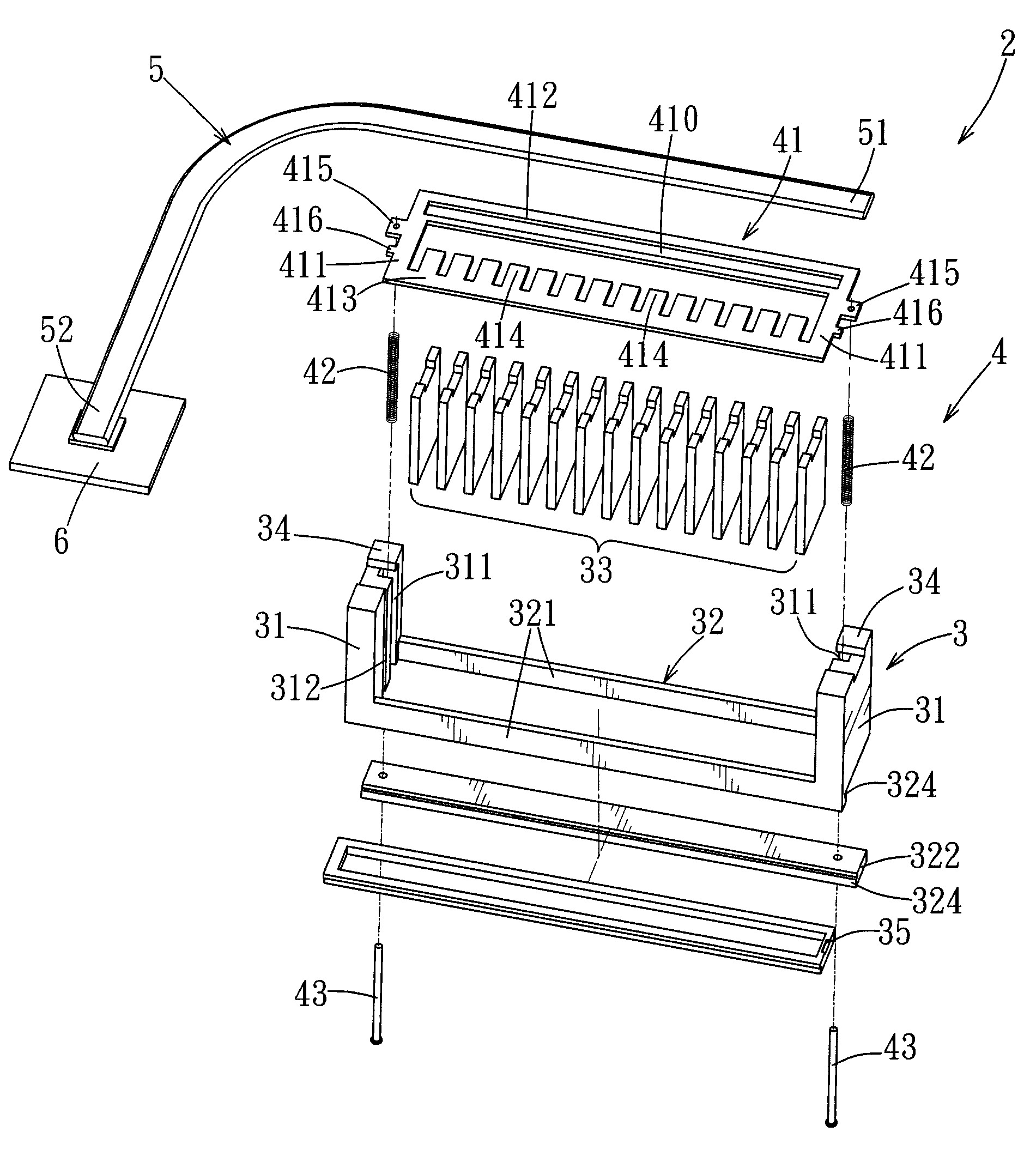
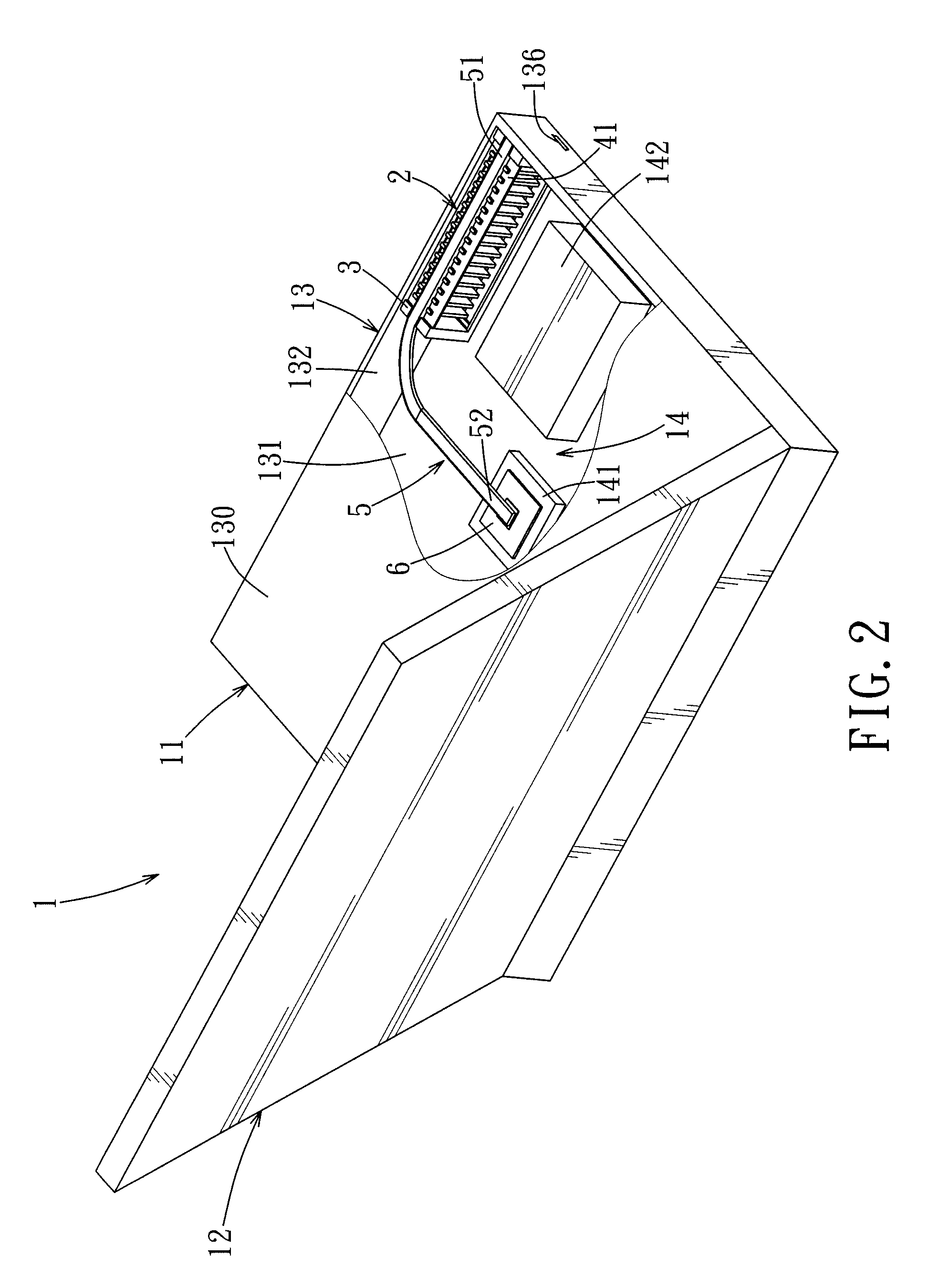
[0023]Referring to FIG. 2, a preferred embodiment of an assembly of an electronic device and a heat-dissipating module according to the present invention is shown to include an electronic device 1 and a heat-dissipating module 2.

[0024]In this embodiment, the electronic device 1 is exemplified as a notebook computer. The electronic device 1 includes a device body 11 and a display 12 connected pivotally to the device body 11. The device body 11 includes a housing 13 and a plurality of electronic components 14 disposed within the housing 13. The electronic components 14 may include a central processing unit (CPU) 141, a hard disk (not shown), a motherboard (not shown), etc. A fan 142 is also mounted in the housing 13.

[0025]Referring to FIGS. 2 and 3, the housing 13 has spaced-apart top and bottom walls 130, 131, and a peripheral wall 132 connected to and interposed between the top and bottom walls 130, 131. The peripheral wall 132 is provided with an air outlet port 133 (which is locat...


PUM


Abstract

In an assembly of an electronic device and a heat-dissipating module, the electronic device includes an electronic component disposed within a housing provided with an air outlet port, and the heat-dissipating module includes a heat-dissipating fin base disposed within the housing adjacent to the air outlet port, and a dust removing mechanism disposed on the heat-dissipating fin base. The heat-dissipating fin base includes two spaced-apart upright sidewalls, and a plurality of heat-dissipating fins arranged between the upright sidewalls. The dust removing mechanism includes a scraping plate disposed between the upright sidewalls and accessible outwardly of the air outlet port. The scraping plate has scraping teeth extending respectively into clearances among the heat-dissipating fins. By manipulating the scraping plate to displace upwardly and downwardly relative to the heat-dissipating fin base, dust that accumulates among the heat-dissipating fins can be scraped off.

Description

CROSS-REFERENCE TO RELATED APPLICATION[0001]This application claims priority of Taiwanese Application No. 097101156, filed on Jan. 11, 2008.BACKGROUND OF THE INVENTION[0002]1. Field of the Invention[0003]The invention relates to a heat-dissipating module, more particularly to a heat-dissipating module with dust-removing functionality and to an assembly of an electronic device and the heat dissipating module.[0004]2. Description of the Related Art[0005]FIG. 1 shows a conventional heat-dissipating module 1 disclosed in U.S. Pat. No. 6,865,082, which includes a plurality of heat-dissipating fins 12 spaced apart from each other, a conducting heat pipe 11, and a conducting pad 10. The conducting heat pipe 11 has one end connected to the heat-dissipating fins 12, and another end connected to the conducting pad 10. The heat-dissipating module 1 is adapted to be disposed in a housing (not shown) of an electronic device, such as a notebook computer, such that the heat-dissipating fins 12 are...

Claims


Application Information

Patent Timeline
Patent Type & Authority Applications(United States)
IPC IPC(8): H05K7/20
CPCF28F19/008F28G1/10G06F1/203H01L23/427H01L2924/0002H01L23/467H01L2924/00
Inventor CHAO, CHIEN-CHIHCHENG, KUEI-YUNG
Owner WISTRON CORP
Why Eureka
Try Eureka