Relay device and relay device controlling method

a relay device and relay technology, applied in data switching details, data switching networks, high-level techniques, etc., can solve the problems of reducing inadequate innovation in controlling both the power consumption, etc., to achieve the control of power consumption and reliability of data relays. , the effect of power consumption

Inactive Publication Date: 2009-07-16
ALAXALA NETWORKS
View PDF8 Cites 30 Cited by
  • Summary
  • Abstract
  • Description
  • Claims
  • Application Information

AI Technical Summary

Benefits of technology

[0011]According to this arrangement, since it is possible to use the first power mode and the second power mode associated with different levels of power consumption by the second group, power consumption can be controlled. Further, between the first and the second power modes, the second priority-handling packet processor will be switched without switching the first priority-handling packet processor. As a result, reliability in first priority data relay can take priority over reliability in second priority data relay. By so doing, both power consumption and reliability of data relay can be controlled.

Problems solved by technology

Often the reduction in performance in the relay device has led to a reduction in the reliability of the data relay.
Note that there has been inadequate innovation in regards to controlling both the reliability of the data relay and the power consumption.

Method used


Image

  • Relay device and relay device controlling method
  • Relay device and relay device controlling method
  • Relay device and relay device controlling method

Examples


embodiment 1

A. Embodiment 1

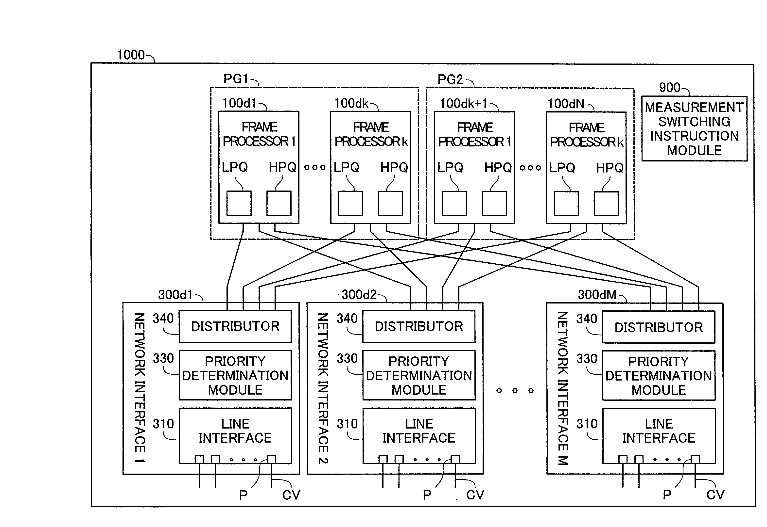
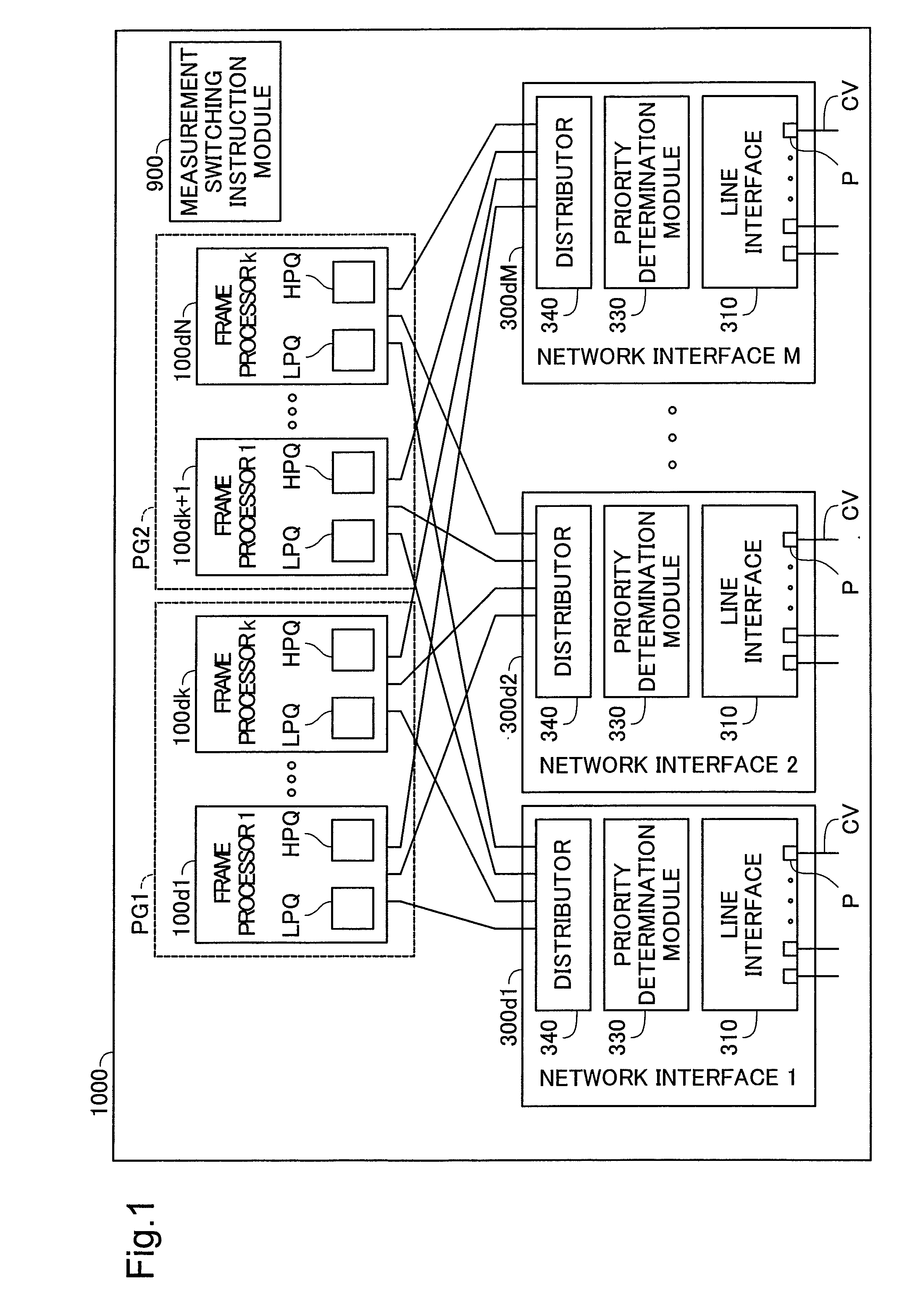
[0040]FIG. 1 is an illustration depicting a switching device 1000 as one embodiment of the invention. This switching device 1000 operates as a so-called Layer 2 switch. Layer 2 corresponds to the second layer (the data link layer) in the OSI (Open System Interconnection) reference model.

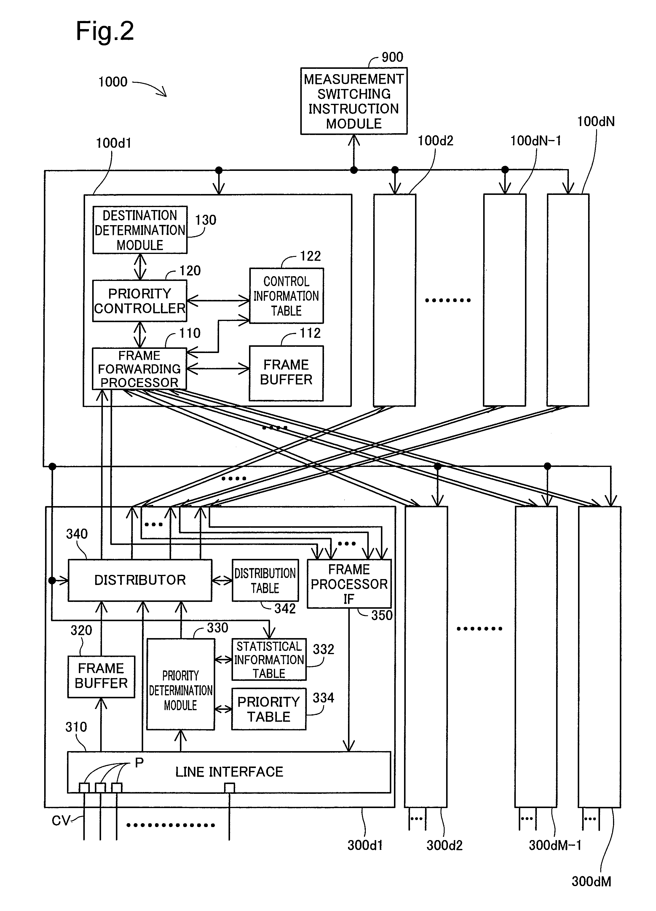
[0041]The switching device 1000 includes a measurement switching instruction module 900; a number N (N is an integer at least 2) of frame processors 100d1 to 100dN; and a number M (M is an integer at least 2) of network interfaces 300d1 to 300dM.

[0042]The configurations of the frame processors 100d1 to 100dN are the same. The configurations of the network interfaces 300d1 to 300dM are also the same. Here, the suffix beginning with the letter “d” (e.g. “d1”) of the reference characters for each of the frame processors 100d1 to 100dN and the network interfaces 300d1 to 300dM is characters identifying the individual module. Hereinbelow, the identifying characters will be omitted in instan...

embodiment 2

B. Embodiment 2

[0119]FIG. 14 is an illustration depicting transition between power modes in Embodiment 2. A point of difference from Embodiment 1 shown in FIG. 13 is that three power modes are available. The configuration of the switching device 1000 is the same as that of Embodiment 1 depicted in FIGS. 1 and 2.

[0120]The first power mode and the second power mode are the same as in Embodiment 1 illustrated in FIG. 13. The third power mode is a mode equivalent to the second power mode with the following modification. The modification is that the second group PG2 can process the high-priority frames HPD in addition to the first group PG1. Specifically, both the first group PG1 and the second group PG2 are employed as candidates for the handling frame processor for the high-priority frames HPD. As a result, in this third power mode, problems with forwarding of the high-priority frames HPD can be suppressed even in instances where the high-priority frame HPD communication load is high.

[...

embodiment 3

C. Embodiment 3

[0133]FIG. 15 is an illustration depicting transition between power modes in Embodiment 3. The only difference from Embodiment 2 shown in FIG. 14 is the different distribution of the low-priority frames LPD in the second power mode. Other processes and arrangements are the same as in Embodiment 2.

[0134]In the second power mode of Embodiment 3, the first group PG1 processes the low-priority frames LPD in addition to the second group PG2. Specifically, both the first group PG1 and the second group PG2 are employed as candidates for the frame processor assigned to handle process the low-priority frames LPD. As a result, problems with forwarding of the low-priority frames LPD can be suppressed.

[0135]Two graphs Ga, Gb are depicted in FIG. 15. The first graph Ga shows temporal change of input load, while the second graph Gb shows temporal change of output amount. Both input load and output amount are expressed in terms of the number of frames per unit of time. These graphs ...


PUM


Abstract

In the first power mode: each packet processor of the second group maintains own operating mode in a first operating mode of relatively low power consumption; and the distributor selects the handling packet processor from the first group for the first priority, and selects the handling packet processor from at least one group excluding the second group for the second priority.
In the second power mode: each packet processor of the second group maintains the own operating mode in a second operating mode of relatively high power consumption; and the distributor selects the handling packet processor from the first group for the first priority, and selects the handling packet processor from at least one group including the second group for the second priority.

Description

CROSS-REFERENCE TO RELATED APPLICATIONS[0001]The present application claims the priority based on Japanese Patent Application No. 2008-2738 filed on Jan. 10, 2008, the disclosure of which is hereby incorporated by reference in its entirety.BACKGROUND[0002]1. Technical Field[0003]The present invention relates to a relay device and to a method of controlling the relay device.[0004]2. Description of the Related Art[0005]Networks including relay devices such as switches and routers have been in use. Recent years have seen dramatic improvements in relay device performances, in order to accommodate larger network scale and increased data traffic. There has been a tendency for the power consumed by the relay devices to increase in accordance with the improved performance Meanwhile, among devices that are connected to networks, there are known devices that can operate in normal operating modes and power saving modes.SUMMARY[0006]Concerning devices operable in a plurality of power modes with...

Claims


Application Information

Patent Timeline
Patent Type & Authority Applications(United States)
IPC IPC(8): H04L12/56H04L12/44H04L45/58H04L47/6275
CPCH04W40/005H04L45/302Y02D30/70
Inventor AKAHANE, SHINICHI
Owner ALAXALA NETWORKS
Why Eureka
Try Eureka