Electrophotographic photoreceptor, photoreceptor supporting device, imaging device and process cartridge

Inactive Publication Date: 2009-07-16
RICOH KK
View PDF5 Cites 7 Cited by
  • Summary
  • Abstract
  • Description
  • Claims
  • Application Information

AI Technical Summary

Benefits of technology

[0014]At least an object of the present invention is to provide, for example, an electrophotographic photoreceptor, which has a simple structure and is low cost, and in which the stability of electrical conduction is improved.
[0016]A further object of the present invention is to reduce an amount of sliding per rotation between the second contact part and an electrical conduction member more easily, to reduce the wear-out of the second contact part, and to improve the long-life of the electrophotographic photoreceptor.
[0018]A further object of the present invention is to provide, for example, an imaging device provided with an electrophotographic photoreceptor, the electrophotographic photoreceptor including few components and having a simple structure and being low cost and in which the stability of electrical conduction being improved.

Problems solved by technology

However, problems arise such as the structure is complex, and the photoreceptor shaft 4 of φ8 mm to φ10 mm is necessary to secure the rigidity, and the cost is high, and wear-out at the second contact part 6b is remarkable, for the photoreceptor supporting device illustrated in FIGS. 6A and 6B.
However, in such a photoreceptor supporting device, due to falling of the cantilevered photoreceptor shafts 8 and 8 or the like, leaning or falling of a shaft center of the electrophotographic photoreceptor occurs, and thus problems arise such as easy occurrence of inclination of an image, easy occurrence of distortion of the image resulting from swinging of the photoreceptor by a rotation, and wear-out at the second contact part 6b.
However, even with this structure, problems still arise, such as a complicated structure and high cost, and many contact parts being required for electrical connection, remarkable wear-out at the second contact part 6b, and decrease of the reliability of the conduction.

Method used


Image

  • Electrophotographic photoreceptor, photoreceptor supporting device, imaging device and process cartridge
  • Electrophotographic photoreceptor, photoreceptor supporting device, imaging device and process cartridge
  • Electrophotographic photoreceptor, photoreceptor supporting device, imaging device and process cartridge

Examples


Embodiment Construction

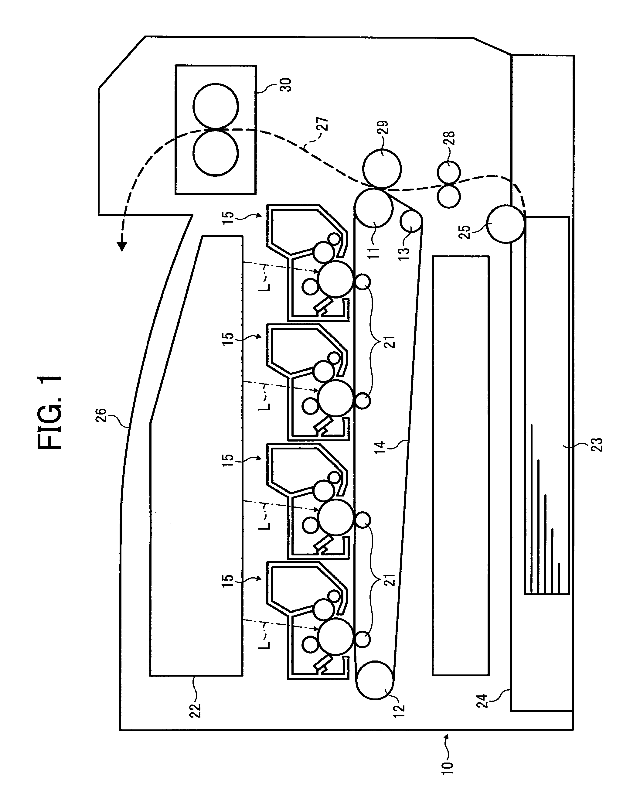
[0029]FIG. 1, reference number 10 represents an imaging device main body.

[0030]In a center of the imaging device main body 10, an intermediate transfer body 14 which is formed in an endless belt shape is wound around three rollers 11 to 13 and is turned by the three rollers. And, four process cartridges 15 with different colors are arranged in a tandem manner on a horizontal part of the intermediate transfer body 14 between the roller 11 and the roller 12. Each of the process cartridges 15 houses a different color toner, and all the process cartridges 15 are formed with a same structure.

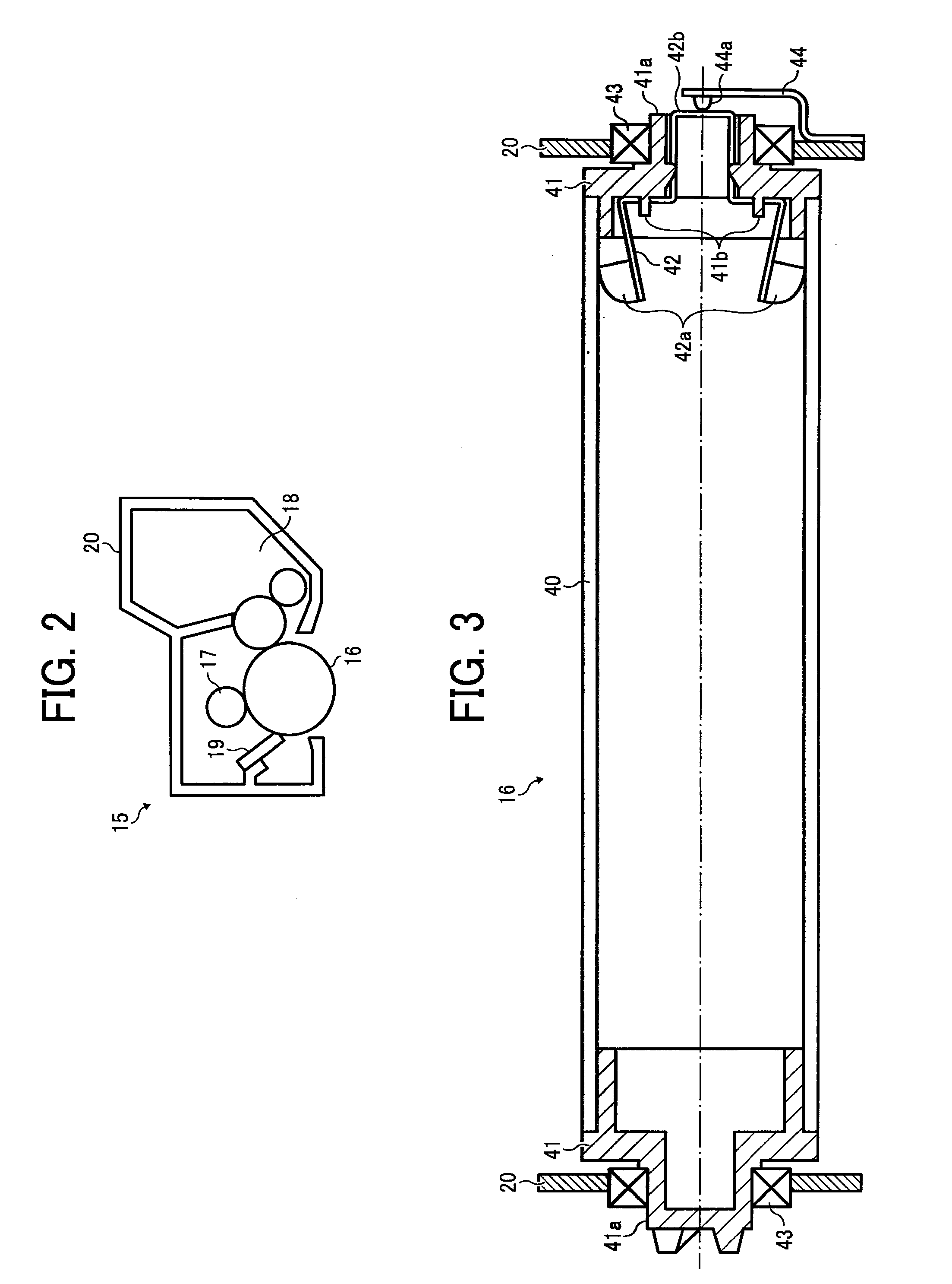
[0031]FIG. 2 illustrates a structure of one of the process cartridges 15.

[0032]As illustrated in the figure, an electrophotographic photoreceptor 16 in a drum shape is provided in each of the process cartridges 15, and a charging device 17 which is configured to charge a surface of the electrophotographic photoreceptor 16 evenly, a developing device 18 which is configured to develop an electrostatic ...


PUM


Abstract

An electrophotographic photoreceptor includes, a cylindrical photoreceptor pipe; at least one flange which is attached to an opening of one end of the photoreceptor pipe, and which is provided with a shaft part projecting outward from the one end at a shaft center position of the photoreceptor pipe; and an earth member which is arranged to penetrate through the shaft part of the at least one flange, and which is provided on its inward side with at least one first contact part which contacts an inner circumference of the photoreceptor pipe, and on its outward side with a second contact part.

Description

CROSS-REFERENCE TO THE RELATED APPLICATION[0001]The entire contents of Japanese patent application No. JP 2008-002740, filed on Jan. 10, 2008, of which the convention priority is claimed in this application are incorporated hereinto by reference.BACKGROUND OF THE INVENTION[0002]1. Field of the Invention[0003]The present invention relates to an electrophotographic photoreceptor, a photoreceptor supporting device, an imaging device and a process cartridge. In particular, the present invention relates to the photoreceptor supporting device which is configured to support the electrophotographic photoreceptor. The present invention farther relates to the imaging device in which an image formed on the electrophotographic photoreceptor is transferred directly or indirectly through an intermediate transfer body, and then the image is recorded on a recording material. The imaging device is used in such as a copy machine, a printer, a facsimile, or a complex machine of those. The present inve...

Claims


Application Information

Patent Timeline
IPC IPC(8): G03G15/00
CPCG03G15/75G03G2221/1609G03G21/06
Inventor KUWABARA, NOBUONAGASHIMA, HIROYUKITANAKA, SHUJIONO, HIROSHIAMEMIYA, KENSHAKUTO, MASAHIKOKOIKE, TOSHIOARAI, YUJIOKAMOTO, MICHIYA
Owner RICOH KK
Why Eureka
Try Eureka