Carabiner

Inactive Publication Date: 2009-07-23
FOUR STRONG
View PDF99 Cites 44 Cited by
  • Summary
  • Abstract
  • Description
  • Claims
  • Application Information

AI Technical Summary

Benefits of technology

[0006]Accordingly, it is the object of this invention to provide an economical, simple to manufacture, easily adjustable, non-slip device on an apex, or load supporting portion of a ca

Problems solved by technology

However, the carabiner has the tendency to slip from side to side on the handle, under the weight of the article being hung from the carabiner and/or because of the motion imparted to the held article.
While U.S. Pat. No. 6,606,769 shows a webbing sewn around the bottom straight portion of a carabiner to preclude slippage of an article, such as a dog leach strap

Method used


Image

  • Carabiner
  • Carabiner
  • Carabiner

Examples


Example

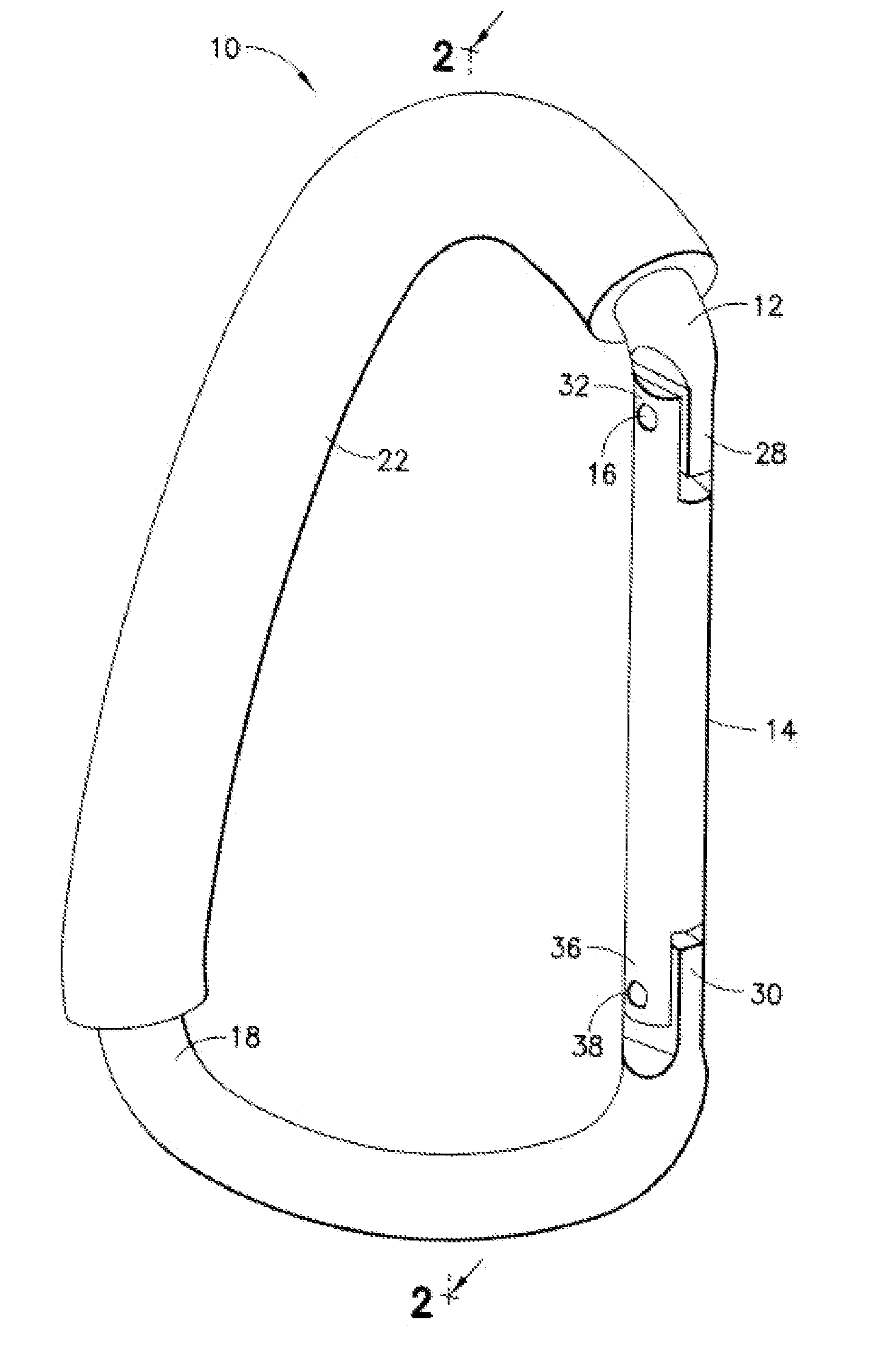
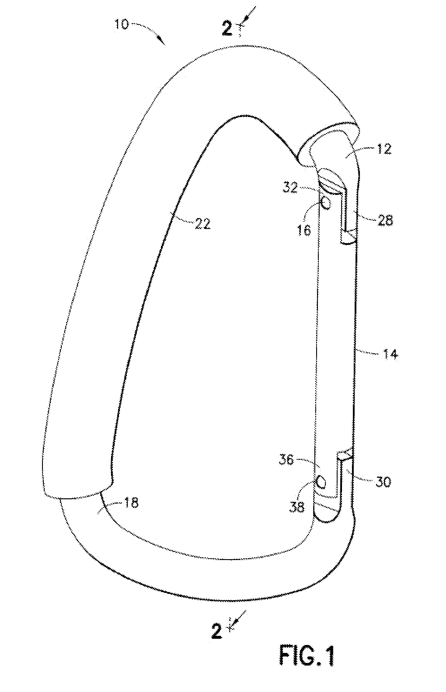
[0019]Referring now to the drawings in detail, wherein like numerals indicate like elements throughout the several views, FIG. 1 illustrates one embodiment of the carabiner 10 of the present invention.

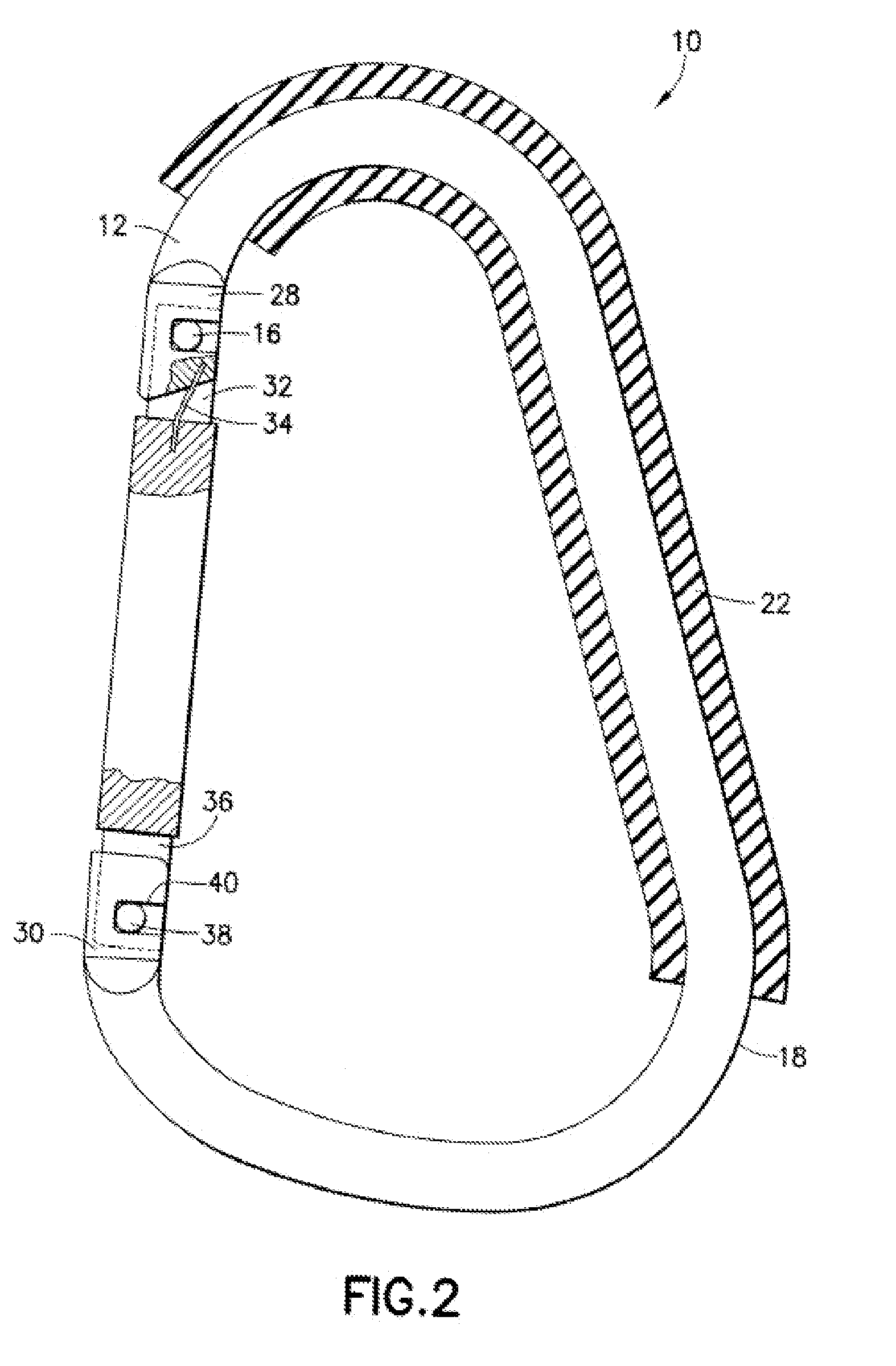
[0020]As shown, carabiner 10 is formed of an essentially C-shaped member 12, and includes a gate member 14, articulated about a pivot pin 16. C-shaped member 12 and gate member 14, when gate member 14 is in closed position as indicated in FIG. 1 are generally oval in configuration, except that the upper portion of C-shaped member 12 is formed with a rounded, shortened, apex portion 18 to serve as a load-bearing surface when the carabiner 10 is hung on a rounded handle 20, as indicated in FIG. 7.

[0021]A rubber sleeve 22 extends about the C-shaped member 12 from a point adjacent to pivot pin 16 and encompassing at least the apex portion 18 of the member 12 as shown in FIG. 1. The sleeve 22 when the carabiner 10 is hung from a rounded handle 20, generates sufficient friction under load to...


PUM


Abstract

A carabiner provided with a load bearing apex portion having a rubber sleeve for preventing side-to-side slippage of said carabiner on a rounded handle of a mobile vehicle such as a stroller or shopping cart.

Description

BACKGROUND OF THE INVENTION[0001]1. Field of the Invention[0002]This invention relates to a carabiner, and more particularly, to a carabiner in the form of a C-shaped structure having an articulated gate member which may be opened and closed to form a secure, hook-like hanger or carrier for a plurality of articles.[0003]2. Description of the Prior Art[0004]Carabiners have long been used in climbing, for example, to hang and hold ropes from used in the climbing process, as shown for example shown in U.S. Pat. Nos. 4,095,316; 4,811,467; 5,005,266; 5,329,675; and 6,606,769; and 6,622,354.[0005]Recently, the function of a carabiner has been expanded to hang articles from a clothing belt, such as keychains, restrain dogs on a leash, or even hang packages, diaper bags, camera bags, or shopping bags from a mobile vehicle such as a baby stroller, shopping cart, or the like, having a cylindrical handle. However, the carabiner has the tendency to slip from side to side on the handle, under th...

Claims


Application Information

Patent Timeline
IPC IPC(8): F16B45/02
CPCF16B45/02Y10T24/45319Y10T24/45346F16B45/023F16B45/024
Inventor ABELS, DAVID L.
Owner FOUR STRONG
Why Eureka
Try Eureka