Eureka AIR delivers breakthrough ideas for toughest innovation challenges, trusted by R&D personnel around the world.

Liquid applying apparatus, method of controlling the same, and ink jet printing apparatus

a technology of liquid application and liquid roller, which is applied in the direction of printing presses, coatings, printing, etc., can solve the problems of difficult to see, disadvantageous displacement of application beads at the start or end position of each application medium, and difficulty in preventing improper application, so as to reduce the wear of the application roller and prevent improper application. , the effect of reducing the number of applications

Inactive Publication Date: 2009-07-23
CANON KK
View PDF14 Cites 5 Cited by
  • Summary
  • Abstract
  • Description
  • Claims
  • Application Information

AI Technical Summary

Benefits of technology

[0019]An object of the present invention is to provide a liquid applying apparatus that enables the viscosity of a liquid to be applied and the condition of supply of the liquid to be detected using conventional mechanisms and without the need for a viscometer or the like, thus allowing prevention of improper application of the liquid to a medium and mitigation of wear of an applying roller or the like, the apparatus having an inexpensive configuration.
[0023]According to the present invention, even if the liquid to be applied is thickened or solidified or the applying liquid is improperly supplied to the liquid holding section, this can be detected without using a viscometer or the like. This enables prevention of improper application of the liquid and mitigation of damage to an applying roller. Consequently, the time, effort, and money required for maintenance of the apparatus can be reduced.

Problems solved by technology

Thus, for example, if applying media of a relatively small size are intermittently conveyed and then a liquid is applied to the applying media, application beads may disadvantageously be displaced at a application start or end position for each applying medium.
Thus, disadvantageously, the applying liquid may be evaporated, or when the posture of the apparatus is changed, the applying liquid may leak.
In particular, for the ink jet printing apparatus such as a printer, when the apparatus is miniaturized, applying the applying mechanisms described in Japanese Patent Laid-Open Nos. 2001-070858, 2002-517341, and H08-072227 (1996) to the apparatus is difficult in view of the leakage of the liquid which may occur when the posture of the apparatus is changed during transportation.
However, the techniques disclosed in the above described patent documents pose the following problems.
The techniques described in Japanese Patent Laid-Open Nos. 2001-070858, 2002-517341, H08-072227 (1996), 2005-254229, and 2006-338100 fail to detect the condition of the applying liquid, for example, thickening or solidification of the liquid resulting from a temporal or environmental change, or a failure to supply the liquid to the applying mechanism.
Thus, the applying operation may be performed with the applying liquid thickened or solidified or with the liquid failing to be sufficiently supplied to the applying mechanism.
As a result, the applying liquid may be improperly applied to the medium.
Furthermore, if the applying operation is continuously performed with the liquid failing to be supplied to the applying mechanism, the applying roller or related components contacting the applying roller may be excessively worn away.
As a result, replacement of parts of the apparatus and maintenance of the apparatus may require much time and cost.
However, this poses a new problem; the addition of viscosity sensing means and the viscosity control means increases the costs of the apparatus.

Method used


Image

  • Liquid applying apparatus, method of controlling the same, and ink jet printing apparatus
  • Liquid applying apparatus, method of controlling the same, and ink jet printing apparatus
  • Liquid applying apparatus, method of controlling the same, and ink jet printing apparatus

Examples


second embodiment

2. Second Embodiment

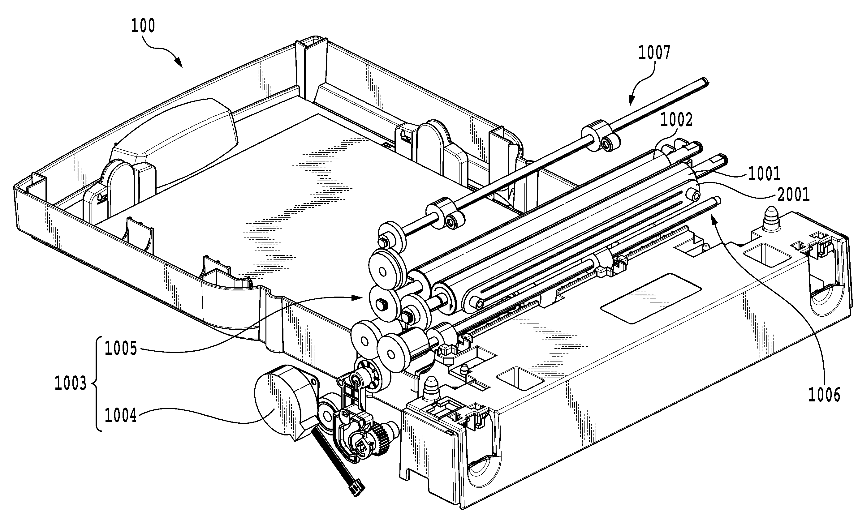
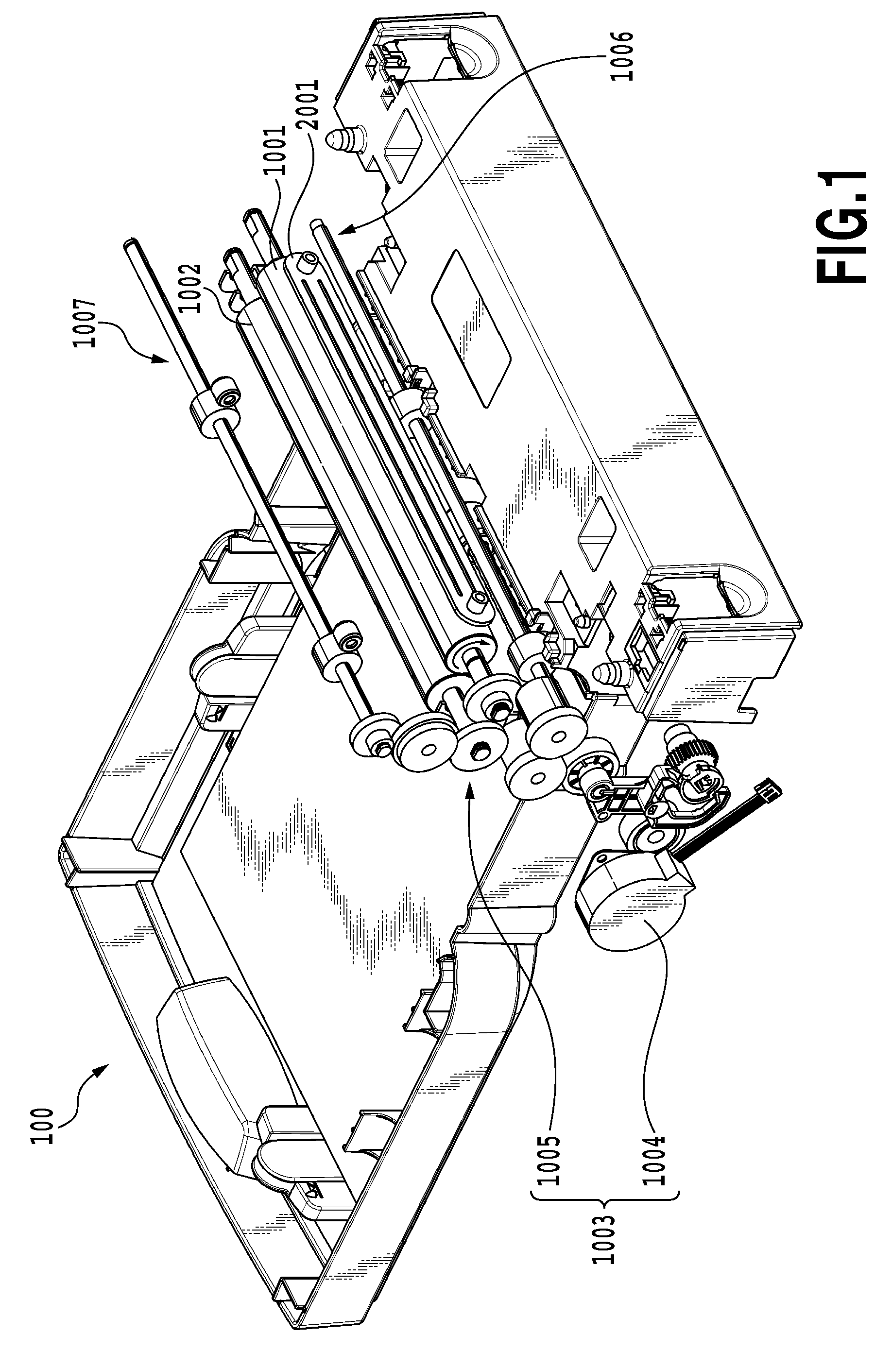
[0171]In the first embodiment, the liquid sensor Y001 is mounted in the second channel in the liquid channel 3000. However, the present invention is applicable to a liquid applying apparatus that avoids installation of the liquid sensor Y001. That is, the present invention is applicable to the configuration shown in FIG. 1 and in which the liquid sensor Y001 is omitted, with the tubes 3103 and 3013a coupled together or integrally formed.

[0172]FIG. 16 is a flowchart showing the operation of a filling step according to the second embodiment of the present invention. As shown in the figure, the second embodiment is different from the above-described first embodiment in the filling step.

[0173]That is, in the filling step, the combination of the open and closed states of the shut-off valves is set for the “circulation” state (S200a). Thus, the liquid applying space S communicates with the buffer tank 3002 via the first and second channels. The pump 3007 is thereafter ...


PUM


Abstract

An object of the present invention is to provide a liquid applying apparatus that enables the viscosity of a liquid to be applied and the condition of supply of the liquid to be detected using conventional mechanisms and without the need for a viscometer or the like, thus allowing prevention of improper application of the liquid to a medium and mitigation of wear of an applying roller or the like, the apparatus having an inexpensive configuration. Thus, according to the present invention, a driving load on an applying roller driving motor is detected when an applying roller is driven. If the driving load is equal to or more than a preset threshold, an operation of re-supplying the liquid is performed by a pump, or an operation of the roller driving motor is stopped.

Description

BACKGROUND OF THE INVENTION[0001]1. Field of the Invention[0002]The present invention relates to a liquid applying apparatus and a liquid applying mechanism that applies a liquid to a print medium to be printed by an ink jet printing apparatus, and specifically, to control of a liquid supply mechanism which is included in the liquid applying mechanism and which supplies the liquid.[0003]2. Description of the Related Art[0004]Spin coaters, roll coaters, bar coaters, and die coaters are known as methods of applying a liquid or a liquid material on common media. These applying methods are based on consecutive application of a liquid to relatively elongate applying media. Thus, for example, if applying media of a relatively small size are intermittently conveyed and then a liquid is applied to the applying media, application beads may disadvantageously be displaced at a application start or end position for each applying medium. Thus, for example, resulting coats may be prevented from b...

Claims


Application Information

Patent Timeline
IPC IPC(8): B05C1/08B05C11/00
CPCB05C1/0813B05C1/083B05C1/0873B41J11/0015
Inventor YOSHINO, HIROSHINAGAHARA, HIDEAKIOHASHI, TETSUYOSEKINO, TAKESHIHAKAMATA, KEISEI
Owner CANON KK
Why Eureka
Eureka Blog
Learn More