Tank withdrawal system with electric and fluidic heating device

a technology of electric and fluid heating and tank withdrawal, which is applied in vehicle heating/cooling devices, exhaust treatment, lighting and heating apparatus, etc., can solve the problems of requiring a large amount of energy, no liquid cleansing solution for the washer system, and liquid freezing at outside temperatures, so as to increase the heating power of the primary electric heating device and increase the heating power of the secondary heating device. , the effect of increasing the heating power

Inactive Publication Date: 2009-07-23
DAVID & BAADER DBK
View PDF28 Cites 41 Cited by
  • Summary
  • Abstract
  • Description
  • Claims
  • Application Information

AI Technical Summary

Benefits of technology

[0054]In some embodiments of the tank withdrawal system, withdrawal units and return units can have identical designs. Thus, a simple modular tank withdrawal system is provided which can be configured by the use of only one module type for withdrawal or return unit. The heating power and the delivery rate of the tank withdrawal system can be determined according to this embodiment by the number of employed withdrawal and/or return units. If, for example, a larger vehicle tank is to be heated or a larger liquid volume is to be provided within a shorter time, the heating power can be increased by the use of a larger number of withdrawal and/or return units. While by the use of more withdrawal units in particular the heating pow...

Problems solved by technology

In vehicle tanks for vehicles which supply a consumer with liquid via a conduit system, a problem arises in that the liquids freeze at outside temperatures that are below the freezing point of the liquid.
In winter, the cleansing solution freezes at low temperatures, so that shortly after a cold start of the vehicle, no liquid cleansing solution for the washer system is available.
The disadvantage of the conventiona...

Method used


Image

  • Tank withdrawal system with electric and fluidic heating device
  • Tank withdrawal system with electric and fluidic heating device
  • Tank withdrawal system with electric and fluidic heating device

Examples


Embodiment Construction

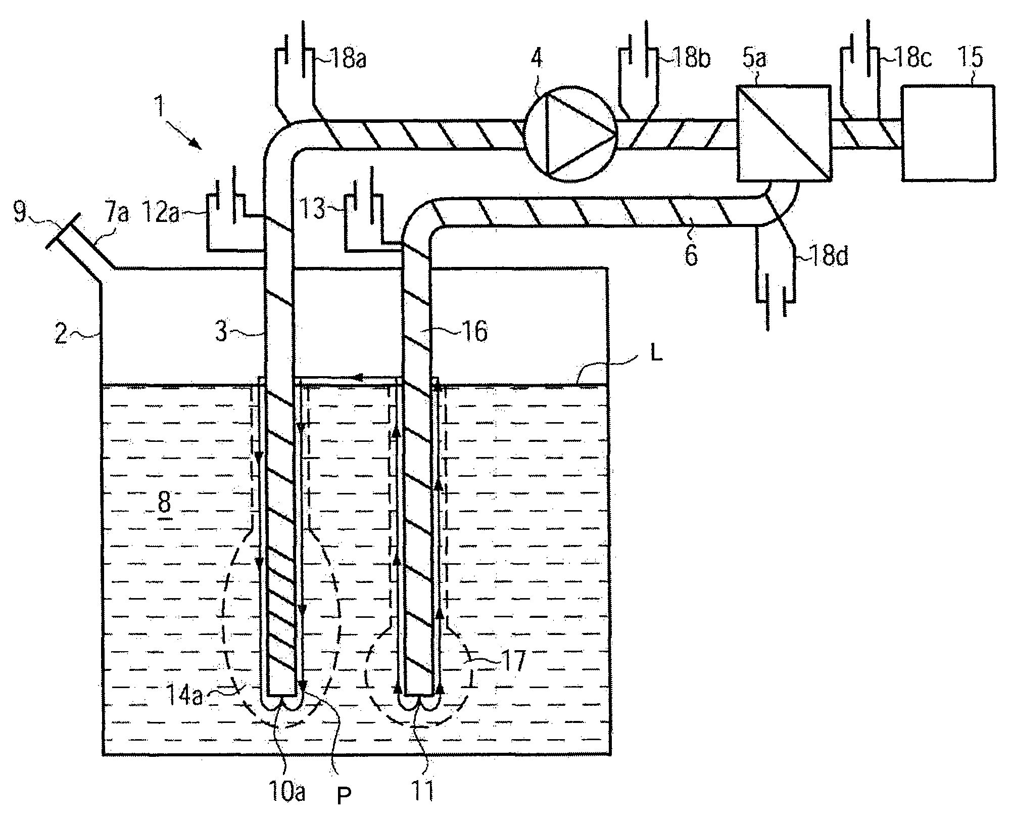
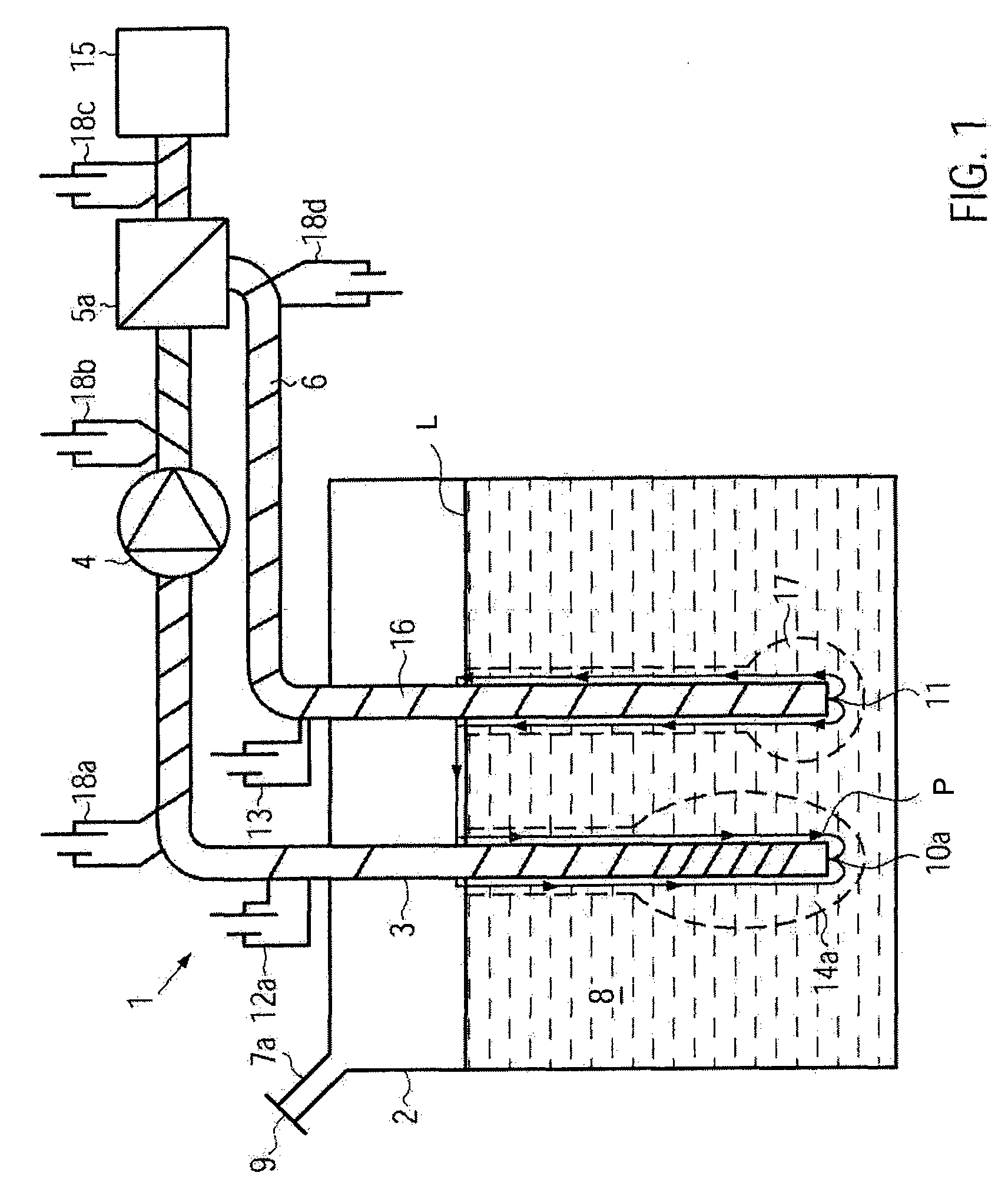
[0068]First, the structure of a tank withdrawal system according to the invention is described with reference to the embodiment of FIG. 1.

[0069]In FIG. 1, a tank withdrawal system 1 with a vehicle tank 2 is shown. The tank withdrawal system 1 comprises a withdrawal conduit 3, a pump 4, a valve 5a and a heating conduit 6. The vehicle tank 2 comprises a filler opening 7a for filling the vehicle tank 2 with a liquid 8. The filler opening 7a of the vehicle tank 2 is closed with a tank cap 9. The withdrawal conduit 3 penetrates the wall of the vehicle tank 2 and immerses into the liquid 8 stored in the vehicle tank. The withdrawal conduit 3 is provided with a withdrawal opening 10a at its end. The heating conduit 6, too, penetrates the wall of the vehicle tank 2. The heating conduit 6 comprises a return conduit 16 provided with a return opening 11 at its end as an extension immersing into the liquid contained in the vehicle tank. The tank withdrawal system 1 comprises a primary heating d...


PUM


Abstract

The invention relates to a tank withdrawal system for a vehicle tank filled with a frozen liquid. The tank withdrawal system comprises a heating system comprising at least one electric heating element as primary heating device and a conduit system provided with at least one withdrawal conduit with a withdrawal opening arranged in the vehicle tank. The cold start volume of the frozen liquid extending around the withdrawal opening can be melted by the primary heating device. To quickly melt a cold start volume while melting off the remaining frozen liquid consuming as minimal amount of energy, the heating system comprises a secondary heating device supplied with a heating fluid and the conduit system comprises at least one heating conduit through which the heating fluid can flow and which is arranged in the liquid in the vehicle tank.

Description

CROSS-REFERENCE TO RELATED APPLICATION[0001]This application claims priority to German Patent Application No. 102008005196.9, filed Jan. 18, 2008, which application is incorporated herein by reference in its entirety.BACKGROUND[0002]1. Technical Field[0003]The invention relates to a tank withdrawal system for a vehicle tank filled with a frozen liquid. The tank withdrawal system includes a heating system comprising at least one electric heating element serving as a primary heating device and includes a conduit system comprising at least one withdrawal conduit with a withdrawal opening arranged in the vehicle tank. A cold start volume of the frozen substance extending around the withdrawal opening can be melted by the electric heating element. The invention further relates to a method of withdrawing a frozen substance from a vehicle tank, wherein the frozen substance is melted in the region around at least one withdrawal opening and the molten liquid is conveyed out of the vehicle ta...

Claims


Application Information

Patent Timeline
IPC IPC(8): F17D1/18B60L1/02B60H1/00F16L53/00
CPCB60S1/487B60S1/488F01N3/2066F01N2290/06Y02T10/24F01N2610/10F01N2610/14F01N2610/1406F01N2610/1473F01N2610/02Y10T137/0391Y10T137/6579Y02A50/20Y02T10/12
Inventor WILDEGGER, CHRISTIAN
Owner DAVID & BAADER DBK
Why Eureka
Try Eureka