Turbulator for a heat exchanger tube, and method of manufacture

a technology of heat exchanger and heat exchanger tube, which is applied in the direction of heat exchange apparatus, tubular elements, lighting and heating apparatus, etc., can solve the problems of limiting the materials which can be used for the turbulator, limiting the heat exchange capacity of the turbulator, and limiting the use of the turbulator. to achieve the effect of increasing the heat exchange capacity

Inactive Publication Date: 2009-07-23
PIERCE DAVID BLAND +3
View PDF6 Cites 43 Cited by
  • Summary
  • Abstract
  • Description
  • Claims
  • Application Information

AI Technical Summary

Benefits of technology

[0022]In certain embodiments the corrugated mesh of material is resilient, so that the corrugations in the mesh can be significantly flattened during insertion into the heat exchanger tube, and once inserted the corrugations can m

Problems solved by technology

Both of these turbulators are limited to use in heat exchanger tubes having a circular cross-section.
Despite the offsetting of the neighboring rows, however, a substantially direct path through the turbulator remains for the working fluid, and so this turbulator does not max

Method used


Image

  • Turbulator for a heat exchanger tube, and method of manufacture
  • Turbulator for a heat exchanger tube, and method of manufacture

Examples


Embodiment Construction

[0023]The invention will now be described in more detail, by way of example, with reference to the accompanying drawings, in which:

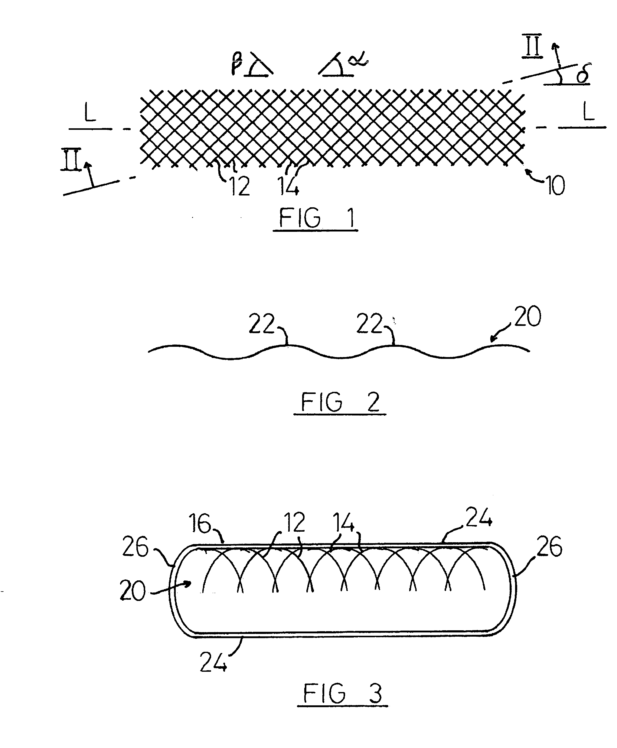
[0024]FIG. 1 shows a plan view of a mesh material prior to corrugating;

[0025]FIG. 2 shows a sectional view along the line II-II of FIG. 1, after the mesh material has been corrugated; and

[0026]FIG. 3 shows a representation of a heat exchanger tube according to the invention, in cross-section.

DETAILED DESCRIPTION

[0027]The mesh material 10 of FIG. 1 is made of metal, and is formed from a first set of wires 12 and a second set of wires 14, the wires in the set of wires 12 all being substantially parallel with each other, as are the wires in the set of wires 14. The wires 12, 14 are interlaced or woven in known fashion.

[0028]The mesh 10 is formed as a strip having a longitudinal axis L which will be aligned with the longitudinal axis of the heat exchanger tube 16 (FIG. 3) when fitted. The wires 12 are arranged at an angle a to the axis L, and the wires 14 a...


PUM

PropertyMeasurementUnit
Angleaaaaaaaaaa
Angleaaaaaaaaaa
Angleaaaaaaaaaa

Abstract

A turbulator for a heat exchanger tube, and a method of manufacturing the heat exchanger tube. The turbulator comprises a mesh, ideally a woven mesh, of material, ideally metallic wires. The mesh is formed into corrugations of a size substantially to fill the heat exchanger tube. The method comprises the steps of: making a mesh of material; forming the mesh into corrugations; and fitting the corrugated mesh into the heat exchanger tube so that the corrugated mesh substantially fills the heat exchanger tube for some or all of its length. The turbulator and method are particularly suited to flat heat exchanger tubes.

Description

CROSS-REFERENCE TO RELATED APPLICATION[0001]This application claims priority under 35 U.S.C. §119 of United Kingdom Patent Application No. 0720627.9 filed Oct. 19, 2007. The disclosure of such United Kingdom patent application is hereby incorporated herein by reference in its entirety, for all purposes.[0002]1. Field of the Invention[0003]This invention relates to a turbulator for a heat exchanger tube, and to a method of manufacturing the heat exchanger tube.[0004]2. Background of the Invention[0005]Often it is necessary to cool a working fluid, and it is known for this purpose to use a heat exchanger. Heat exchangers often comprise one or more metallic tubes suspended between two tube plates. Usually, the working fluid to be cooled, which may for example be water or oil, flows through the tubes, whilst the coolant passes around and between those tubes, the working fluid giving up its latent heat to the tubes and thus to the coolant.[0006]The effective surface area of a tube can be...

Claims


Application Information

Patent Timeline
IPC IPC(8): F28F13/12B23P15/26
CPCF28D2021/0049F28D2021/0098F28F1/405Y10T29/49391F28F21/067F28F21/08F28F13/12
Inventor PIERCE, DAVID BLANDPIERCE, GERRARD M.PIERCE, PAUL L.NIEKRASZ, JAMES
Owner PIERCE DAVID BLAND
Why Eureka
Try Eureka