

Metal gasket
- Summary
- Abstract
- Description
- Claims
- Application Information
AI Technical Summary
Benefits of technology
Problems solved by technology
Method used
Image

Examples
first embodiment
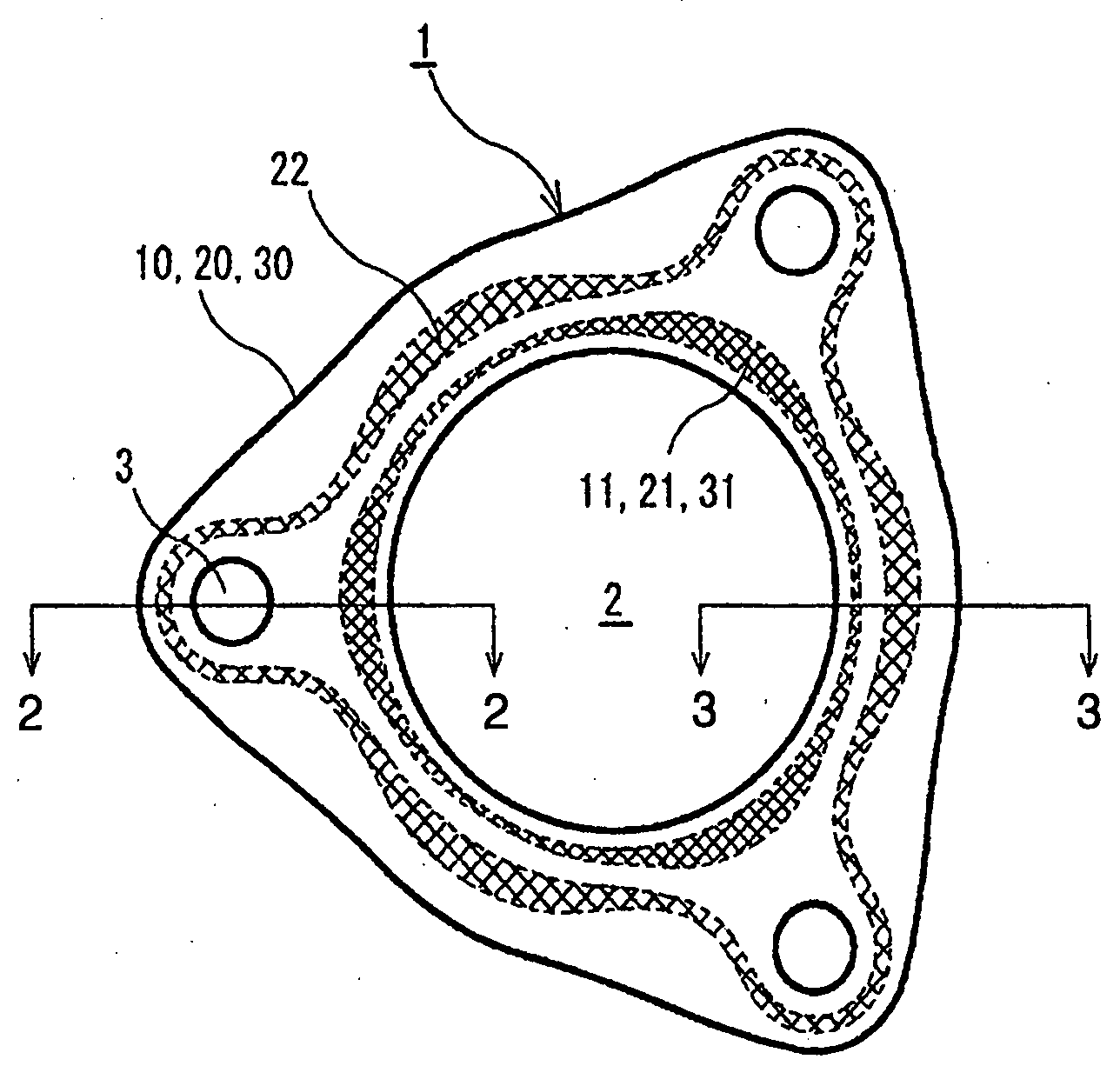
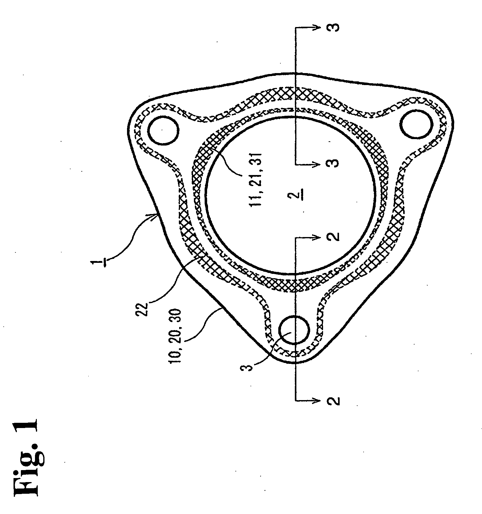
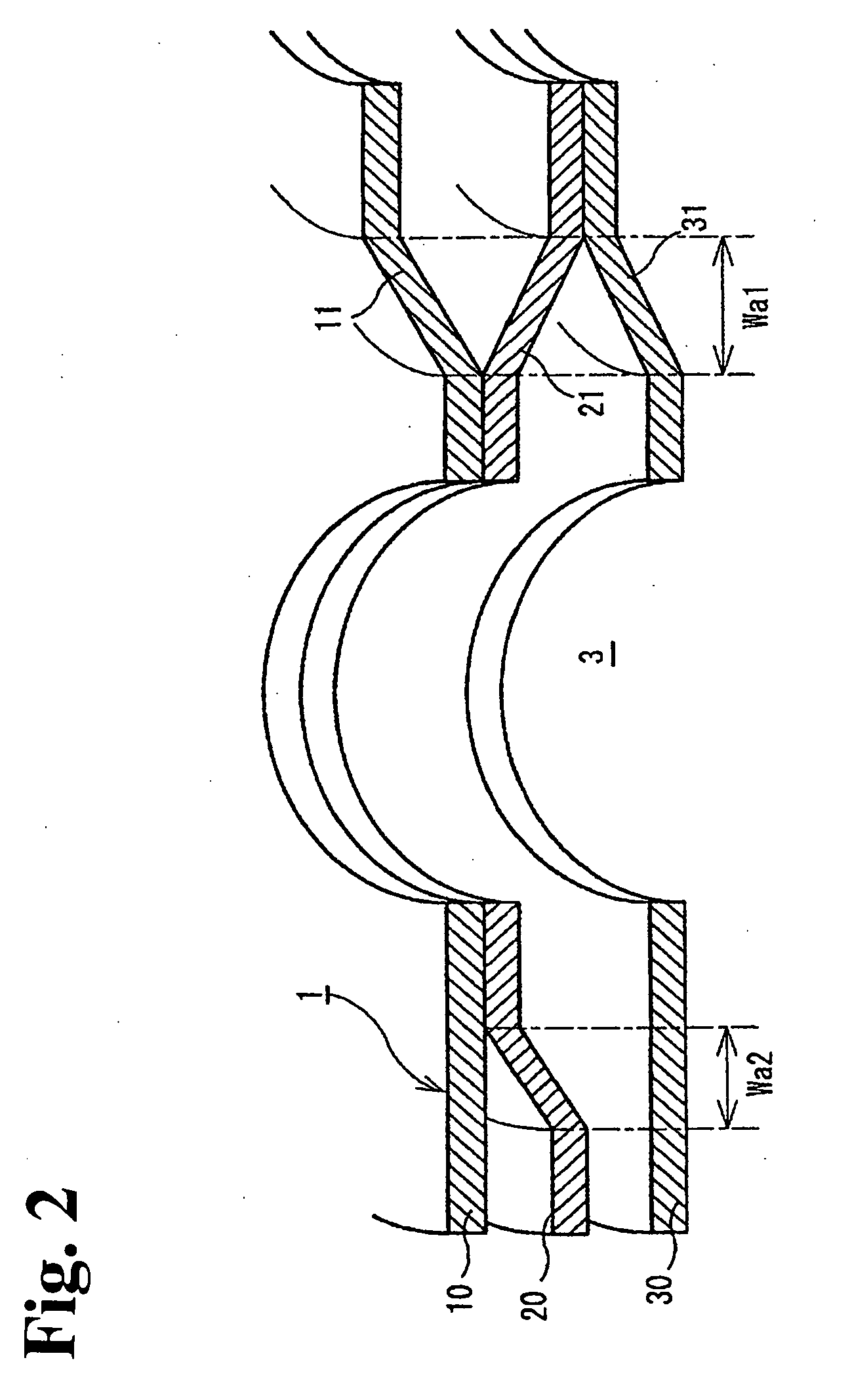
[0032]In the metal gasket 1 of the first embodiment shown in FIGS. 1 to 3, in addition to the above-mentioned two sheets of the first and second metal structural plates 10, 20, the third metal structural plate 30 is laminated. In the third metal structural plate 30, in a plan view, the inner-periphery side bead 31 is formed with the half bead with the slope such that an inner periphery side becomes abutted against the first metal structural plate 10 and that an outer periphery side thereof inclines toward the opposite side of the first metal structural plate 10. The inner-periphery side bead 31 overlaps with the inner-periphery side beads 11, 21 of the first and second metal structural plates 10, 20 in a plan view.
second embodiment
[0033]Also, in the metal gasket 1A of the second embodiment shown in FIGS. 5, 6, in addition to the above-mentioned two sheets of first and second metal structural plates 10, 20, fourth and fifth metal structural plates 10A, 20A, which have the same shape, are laminated in such a way as to be symmetric to the laminated surface. According to the structure, in a plan view, the inner-periphery side beads 11, 21, 21A, 11A overlap, and the outer-periphery side beads 22, 22A overlap.
[0034]According to the metal gasket 1 (or 1A), in the inner-periphery side beads 11, 21, 31 (or 11, 21, 21A, 11A) forming a primary seal, the neighboring portion of the bolt hole 3, wherein the impact of the bolt fastening force is strong and the sealing surface pressure is apt to be large, receives compressibility and a low surface pressure by reducing the compression resistance. Also, the portion between the bolt holes 3, wherein the impact of the bolt fastening force is weak and the sealing surface pressure...
PUM
 Abstract
Description
Claims
Application Information