Imaging optical system for camera and video telephony camera employing the same

a technology of optical system and optical system, which is applied in the field of imaging optical system for camera and video telephony camera using, can solve the problems of barrel-shaped images, low image quality of 1/7′′ cif camera modules, and inability to adapt to small-sized, lightweight, low-cost applications, etc., and achieves a large back focal length and high telecentricity.

Inactive Publication Date: 2009-07-23
HANWHA TECHWIN CO LTD
View PDF2 Cites 3 Cited by
  • Summary
  • Abstract
  • Description
  • Claims
  • Application Information

AI Technical Summary

Benefits of technology

[0009]The present invention also provides an imaging optical system for a camera, which can provide high telecentricity and a large back focal length (BFL), and a video telephony camera employing the imaging optical system.

Problems solved by technology

Conventional 1 / 7″ VGA camera modules have an angle of view of about 60° that is extremely narrow for video communication and are not suitable for small-sized, lightweight, and low cost applications.
1 / 7″ CIF camera modules have low image quality and severe distortion of over 5% that causes barrel-shaped images.
These characteristics are not suitable for satisfactory video communication.
In particular, image sensors that become increasingly compact with the miniaturization of mobile devices suffer from shading.

Method used


Image

  • Imaging optical system for camera and video telephony camera employing the same
  • Imaging optical system for camera and video telephony camera employing the same
  • Imaging optical system for camera and video telephony camera employing the same

Examples


embodiment 1

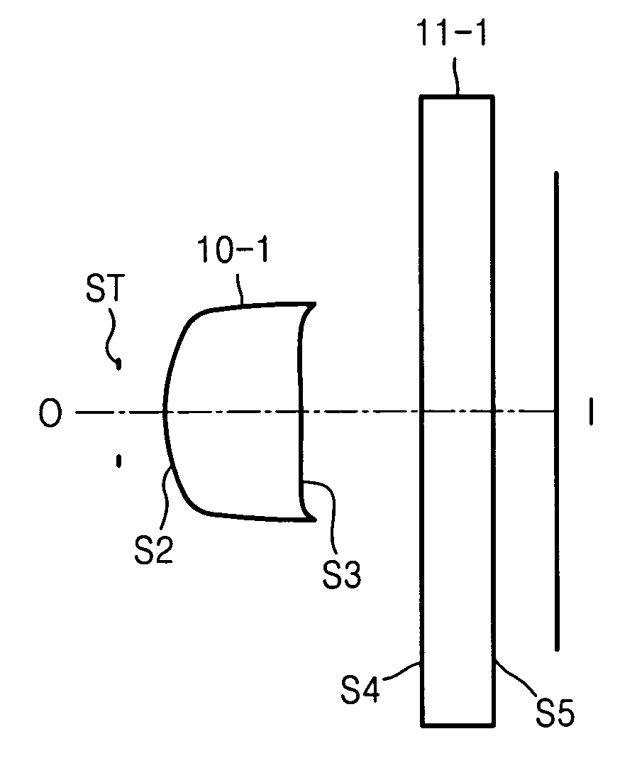
[0033]FIG. 1 illustrates an imaging optical system for a video telephony camera according to Embodiment 1 of the present invention.

f: 1.2 Fno: 3.2 ω: 33.12RDnndvdOBJ:INFINITYINFINITYST:INFINITY0.185000S2:0.803110.5600001.51962.1ASP:K:−0.184802A:−0.911278E+00B:0.659388E+02C:−0.114181E4-04D:0.739397E+04E:0.123190E+05F:−0.341265E+06G:0.971385E+06H:0.105746E+06J:0.364568E+07S3:−2.158620.548409ASP:K:−1501.550393A:−.218624E+01B:0.564299E+02C:−0.392159E+03D:0.285445E+03E:0.792600E+04F:0.105250E+05G:−0.215591E+06H:−0.602321E+06J:0.449663E+07S4:INFINITY0.3000001.51664.2S5:INFINITY0.167227IMG:INFINITY0.000000

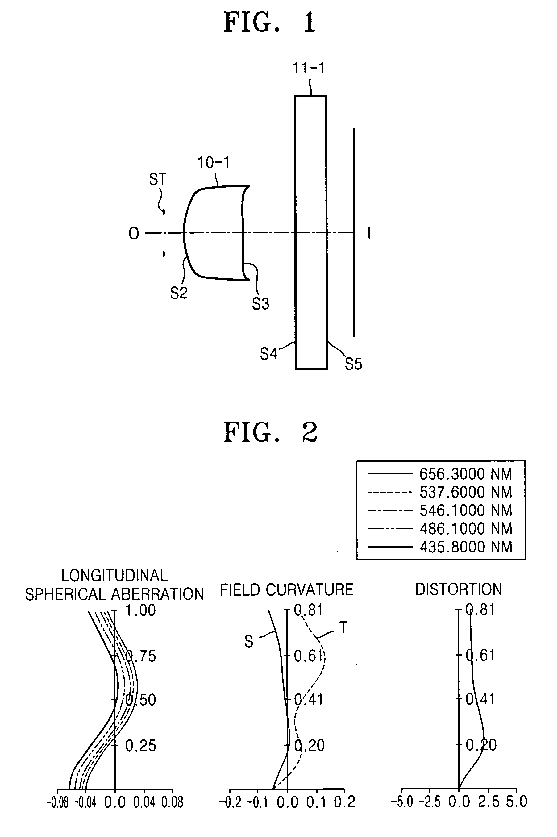
[0034]FIG. 2 illustrates spherical aberration, field curvature, and distortion of the imaging optical system according to Embodiment 1. Referring to FIG. 2, spherical aberration curves show spherical aberration values for C-line, e-line, and F-line that are respectively 656.3 nm, 546 nm, and 486.1 nm. Field curvature curves S and T in the second diagram respectively show tangential field ...

embodiment 2

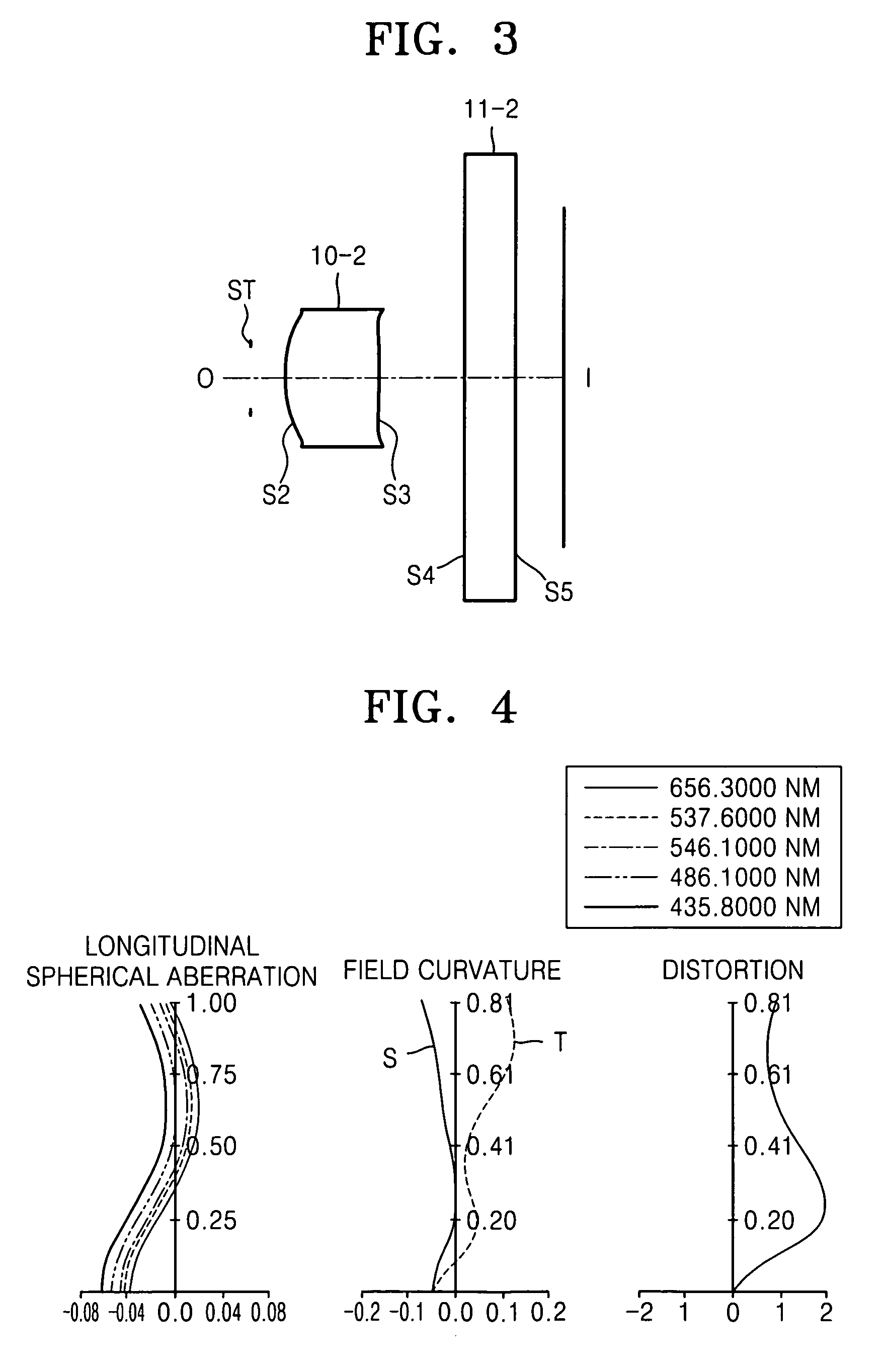
[0035]FIG. 3 illustrates an imaging optical system for a video telephony camera according to Embodiment 2 of the present invention.

f: 1.22 Fno: 3.2 ω: 32.68RDnndvdOBJ:INFINITY250.000000ST:INFINITY0.200000S2:0.808230.5500001.51962.1ASP:K:0.470962A:−0.180076E+00B:0.173976E+02C:−0.180876E+03D:0.568593E+03E:−.0132799E+04F:0.115904E+05G:0.974523E+05H:0.198648E+06J:−.739985E+07S3:−2.293970.548200ASP:K:−1273.835331A:−0.121126E+01B:0.319962E+02C:−0.154159E+03D:−0.165218E+03E:0.360086E+04F:0.717007E+04G:−0.108718E+06H:0.365225E+05J:0.926656E+06S4:INFINITY0.3000001.51664.2S5:INFINITY0.195639IMG:INFINITY0.000000

[0036]FIG. 4 illustrates spherical aberration, field curvature, and distortion of the imaging optical system of Embodiment 2.

embodiment 3

[0037]FIG. 5 illustrates an imaging optical system for a video telephony camera according to Embodiment 3 of the present invention;

f: 1.23 Fno: 3.2 ω: 32.66RDnndvdOBJ:INFINITY250.000000ST:INFINITY0.200000S2:0.848980.5500001.51962.1ASP:K:0.569636A:0.358835E+00B:0.440889E+01C:−0.812760E+02D:0.803837E+03E:−0.396404E+04F:0.413812E+04G:0.338937E+04H:0.372890E+05J:−.104598E+06S3:−2.042490.548100ASP:K:−835.419925A:−0.148210E+01B:0.338642E+02C:−0.162500E+03D:−0.198801E+03E:0.367131E+04F:0.869016E+04G:−0.101747E+06H:0.322068E+05J:0.519856E+06S4:INFINITY0.3000001.51664.2S5:INFINITY0.217263IMG:INFINITY0.000000

[0038]FIG. 6 illustrates spherical aberration, field curvature, and distortion of the imaging optical system of Embodiment 3.


PUM


Abstract

An imaging optical system for a camera and a video telephony camera employing the imaging optical system. The imaging optical system includes a stop and a first lens that are sequentially arranged from an object side. The first lens has a positive refractive power and two convex aspherical surfaces and satisfies LB / f>0.88 and LT / LB<1.71 wherein LT is the distance along the optical axis from the stop to the image plane of the imaging optical system, f is the total focal length of the imaging optical system, and LB is the distance along the optical axis between the surface of the first lens facing the image side and the image plane of the imaging optical system.

Description

CROSS-REFERENCE TO RELATED PATENT APPLICATION[0001]This application claims the benefit of Korean Patent Application No. 10-2008-0005760, filed on Jan. 18, 2008, in the Korean Intellectual Property Office, the disclosure of which is incorporated herein in its entirety by reference.BACKGROUND OF THE INVENTION[0002]1. Field of the Invention[0003]The present invention relates to an imaging optical system for a camera and a video telephony camera employing the imaging optical system.[0004]2. Description of the Related Art[0005]Digital or video cameras having solid state imaging sensors such as Charge Coupled devices (CCDs) or Complimentary Metal Oxide Semiconductors (CMOSs) have become popular in recent years. In particular, demands for mega-pixel camera modules are increasing and digital cameras with resolutions of 5 megapixels or more are now commonplace. Optical imaging devices, such as digital cameras or mobile phone cameras using CCDs or CMOSs, are required to be small-sized, lightw...

Claims


Application Information

Patent Timeline
Patent Type & Authority Applications(United States)
IPC IPC(8): H04N7/14H04N5/225
CPCG02B9/02H04N5/2254G02B13/009G02B13/0025G02B9/04G02B3/02
Inventor CHOI, BYEONG-HA
Owner HANWHA TECHWIN CO LTD
Why Eureka
Try Eureka