
Project-type three-dimensional image reproducing apparatus

a three-dimensional image and reproducing apparatus technology, applied in the field of project-type three-dimensional image reproducing apparatus, can solve the problems of large-scale apparatus and inconvenience, loss of stereoscopic effect, and optical configuration required to perform conventional stereographs with naked eyes, so as to prevent crosstalk between adjacent lenses or adjacent hologram optical elements, stable stereoscopic image, and avoid distortion or shift of images

Inactive Publication Date: 2009-07-23
PANASONIC CORP
View PDF5 Cites 12 Cited by
  • Summary
  • Abstract
  • Description
  • Claims
  • Application Information

AI Technical Summary

Benefits of technology

[0015]The present invention has been conceived in light of the above problems and aims at providing a projection-type three-dimensional image reproducing apparatus that enables stable provision of a three-dimensional image display by preventing occurrence of crosstalk between adjacent lenses or adjacent hologram optical elements and eliminating shift of a three-dimensional image when a steroscopic image is reproduced by use of a lenticular lens array, a fly-eye lens array, or a hologram optical element.
[0019]According to the present invention, occurrence of crosstalk between adjacent lenses or adjacent hologram optical elements can be prevented. Thus, an image that should not originally be displayed is not displayed on the adjacent lens or the adjacent hologram optical element. As a consequence, distortion or shift of an image is prevented. Therefore, there is yielded an advantage of the ability to implement a three-dimensional image reproducing apparatus capable of providing a stable stereoscopic image, enhanced image quality of a three-dimensional image display, and an enhanced stereoscopic effect.

Problems solved by technology

Hence, the display device in principle involves a problem of loss of a stereoscopic effect when the positions of the right and left eyes of the observer deviate from the horizontal direction.
However, the method entails a large-scale apparatus and inconvenience of equiping an observer with a marker to sense the positions of eyes and the position of a face.
However, the optical configuration required to perform conventional stereograph with naked eye has a problem of cross-talk between lenses.
This fact causes the cross-talk between lenses.
For this reason, crosstalk greatly affects quality of a stereoscopic display.
However, it is very difficult to efficiently manufacture a lens array having a small curvature radius.
However, there arises a problem of a reproduced three-dimensional image becoming dark and three-dimensional reproduction being hindered by a contour effect of the shield mask.

Method used


Image

  • Project-type three-dimensional image reproducing apparatus
  • Project-type three-dimensional image reproducing apparatus
  • Project-type three-dimensional image reproducing apparatus

Examples


Embodiment Construction

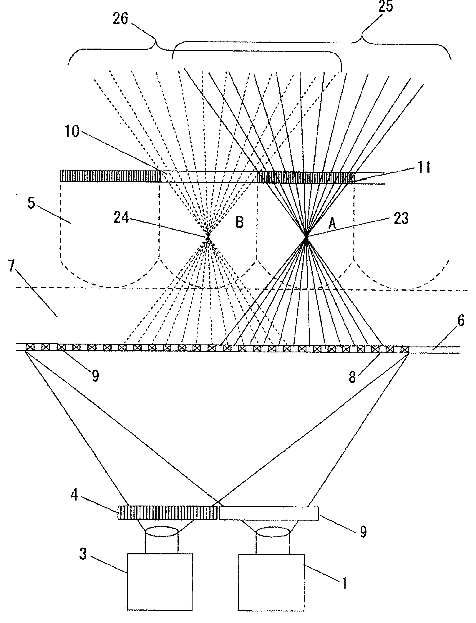
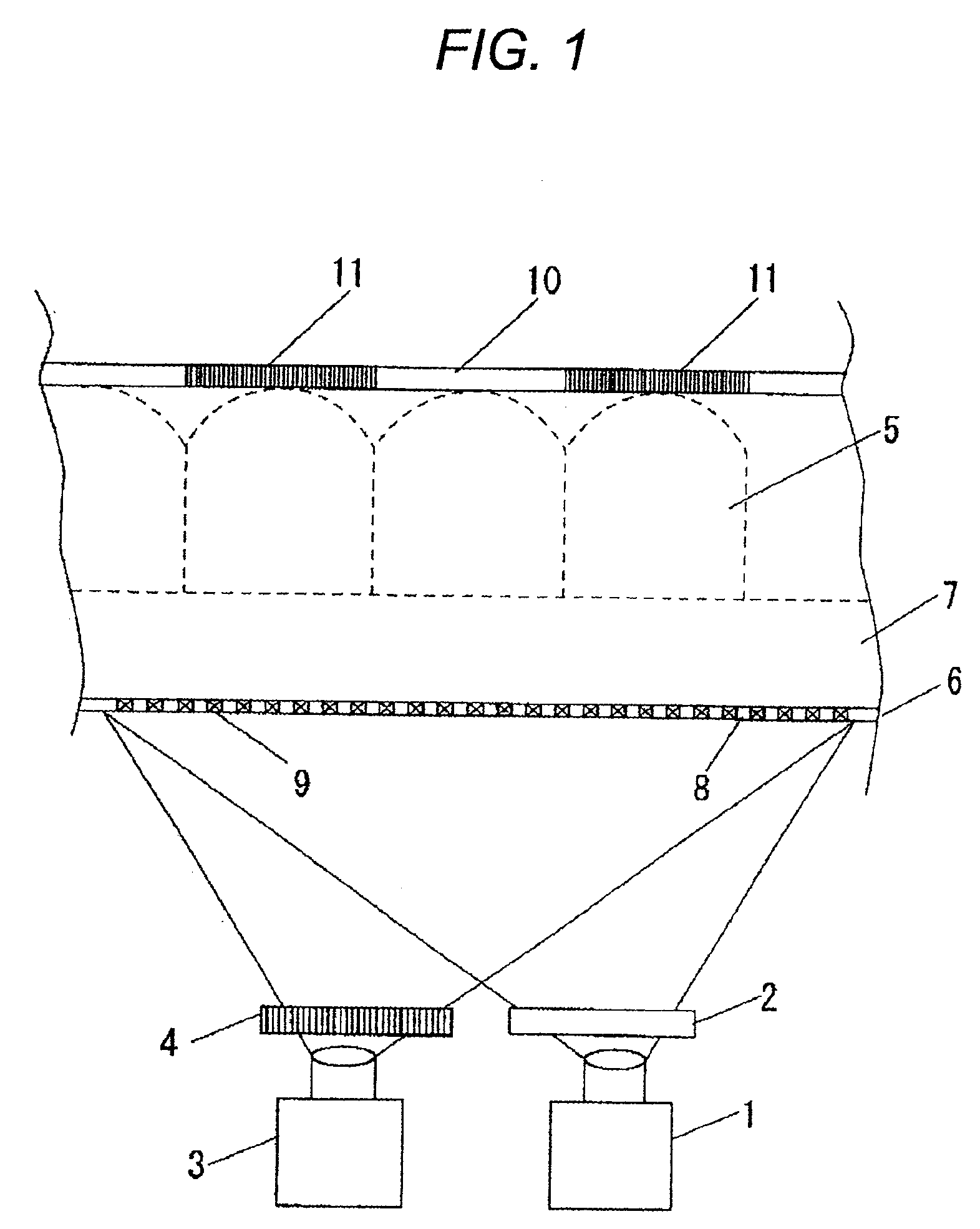
[0025]The present invention can be applied to a display method, such as integral photography, a lenticular method, a parallax barrier method, and an ultra-multiple lens method, and the like, which enables provision of stereogram display with naked eye by combination of two-dimensional image information including parallax information, a lenticular lens array, a slit-shaped barrier such as liquid crystal, and a fly-eye lens or a hologram optical element. A preferred embodiment of a projection-type three-dimensional image reproducing apparatus of the present invention will be described hereunder in detail by reference to the drawings. Respective embodiments illustrate the case of use of a lens array. However, the same also applies to the case of use of a hologram optical element.

[0026]FIG. 1 is a view showing a system configuration of an optical system that is the principal part of a projection-type three-dimensional image reproducing device of an embodiment of the present invention.

[0...


PUM


Abstract

The present invention provides a projection-type three-dimensional image reproducing apparatus that enables stable provision of a three-dimensional image display by preventing occurrence of crosstalk between adjacent lenses or adjacent hologram optical elements and eliminating shift of a three-dimensional image when a steroscopic image is reproduced by use of a lenticular lens array, a fly-eye lens array, or a hologram optical element. The three-dimension image reproduce apparatus includes an array of adjoining optical elements, which is an array of lenticular lens, a fly-eye lens array or an array of hologram optical elements, and a cross-talk prevent part preventing cross-talk between the adjoining optical elements.

Description

BACKGROUND OF THE INVENTION[0001]The present invention relates to a three-dimensional image reproducing apparatus that reproduces a stereographic image by use of a lenticular lens array, a fly-eye lens array, or a hologram optical element.[0002]A parallel-vision random dot stereogram method under which a right-side stereographic image including binocular parallax is viewed with a right eye and which a left-side stereographic image including binocular parallax is viewed with a left eye, a stereoscope method under which a view is acquired by use of eyeglasses with a liquid-crystal shutter or by using one lens for a right eye and another lens for a left eye, and an anaglyph method under which a red binocular parallax picture and a blue binocular parallax picture, both of which differ from each other in only color, are viewed by use of red-and-blue eyeglasses, and other methods, have been known as methods for displaying three-dimensional image information since old times. However, when ...

Claims


Application Information

Patent Timeline
IPC IPC(8): G02B27/26G02B30/25G02B30/27H04N13/305H04N13/307H04N13/363
CPCG02B27/2214H04N13/0459H04N13/0406H04N13/363H04N13/307G02B30/27H04N13/305
Inventor KUBARA, TAKASHI
Owner PANASONIC CORP
Learn More