Optical deflector

a technology of optical deflectors and deflectors, which is applied in the direction of piezoelectric/electrostrictive/magnetostrictive devices, piezoelectric/electrostrictive/magnetostriction machines, instruments, etc., can solve the problems of difficult to measure the twist displacement with a good s/n ratio, increase system size, and complex structure, etc., to achieve easy installation of optical deflectors, improve yield, and relatively easy manufacturing

Active Publication Date: 2009-07-23
STANLEY ELECTRIC CO LTD
View PDF5 Cites 45 Cited by
  • Summary
  • Abstract
  • Description
  • Claims
  • Application Information

AI Technical Summary

Benefits of technology

[0071]According to one or more of these aspects of the present invention, because the optical deflector can be formed integrally using a semiconductor planer process and a MEMS process, the manufacturing of the optical deflector is relatively easy and it is possible to mass-produce the optical deflector with an improved yield. Furthermore, in installing the optical deflector in a device, because it is possible to form the optical deflector integrally with the entire device by the patterning process using a semiconductor planer process and a MEMS process, it is relatively easy to install the optical deflector in other devices, and it is possible to reduce the overall size of the device and to mass-produce it.

Problems solved by technology

However, in this technique, the system size is increased.
However, due to the built-in piezoresistance elements or strain gauges, a complex structure would result.
However, because the twist displacement of the torsion bar is minute, it is difficult to measure the twist displacement with a good S / N ratio.
Furthermore, because the position of the piezoelectric sensor is close to the piezoelectric actuator, a crosstalk of the sensor signal with the driving signal of the piezoelectric signal is a problem.

Method used


Image

  • Optical deflector
  • Optical deflector
  • Optical deflector

Examples


first embodiment

[0080]With reference to FIGS. 1 through 5, an optical deflector according to a first embodiment of the present invention is described.

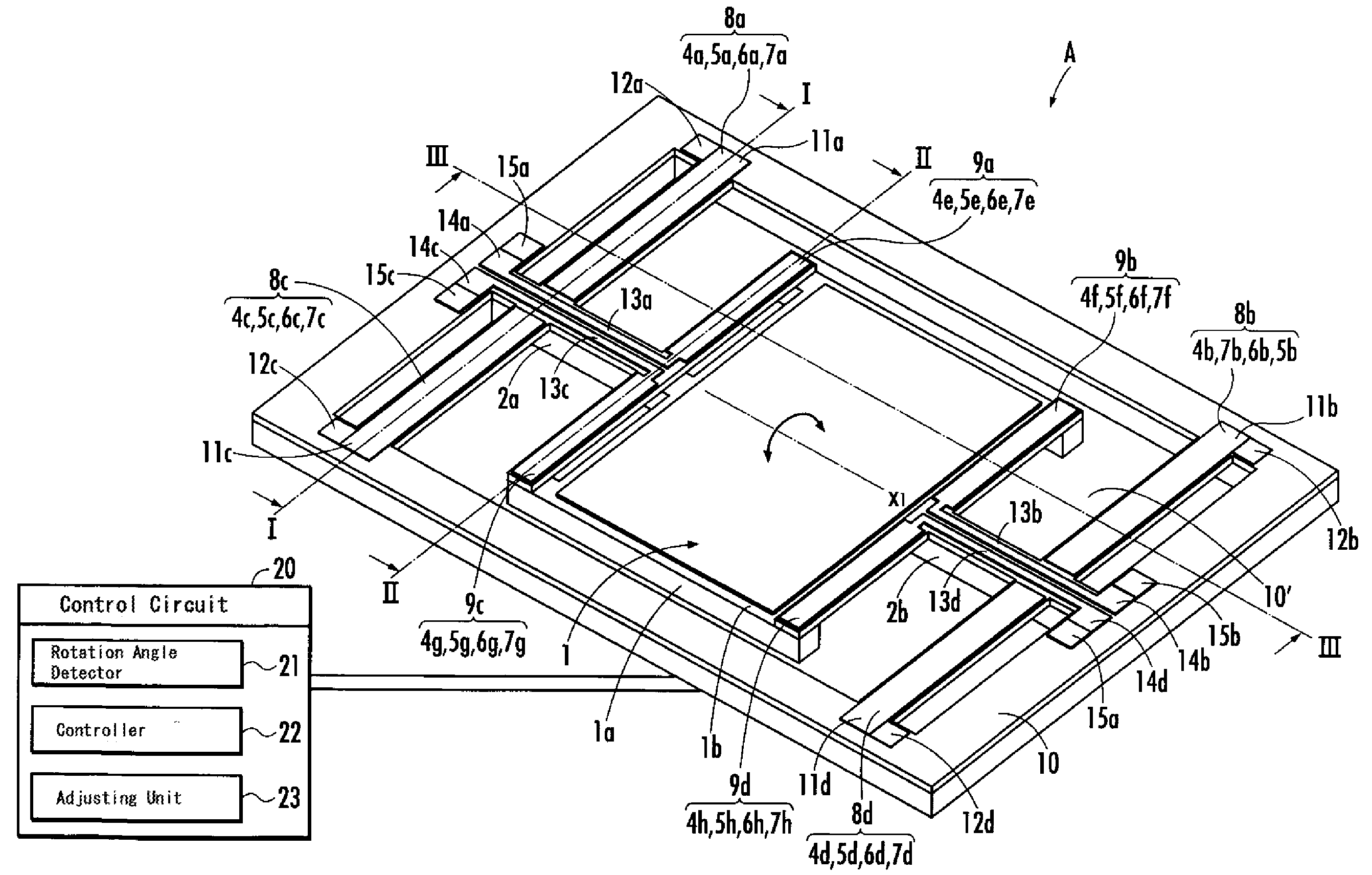
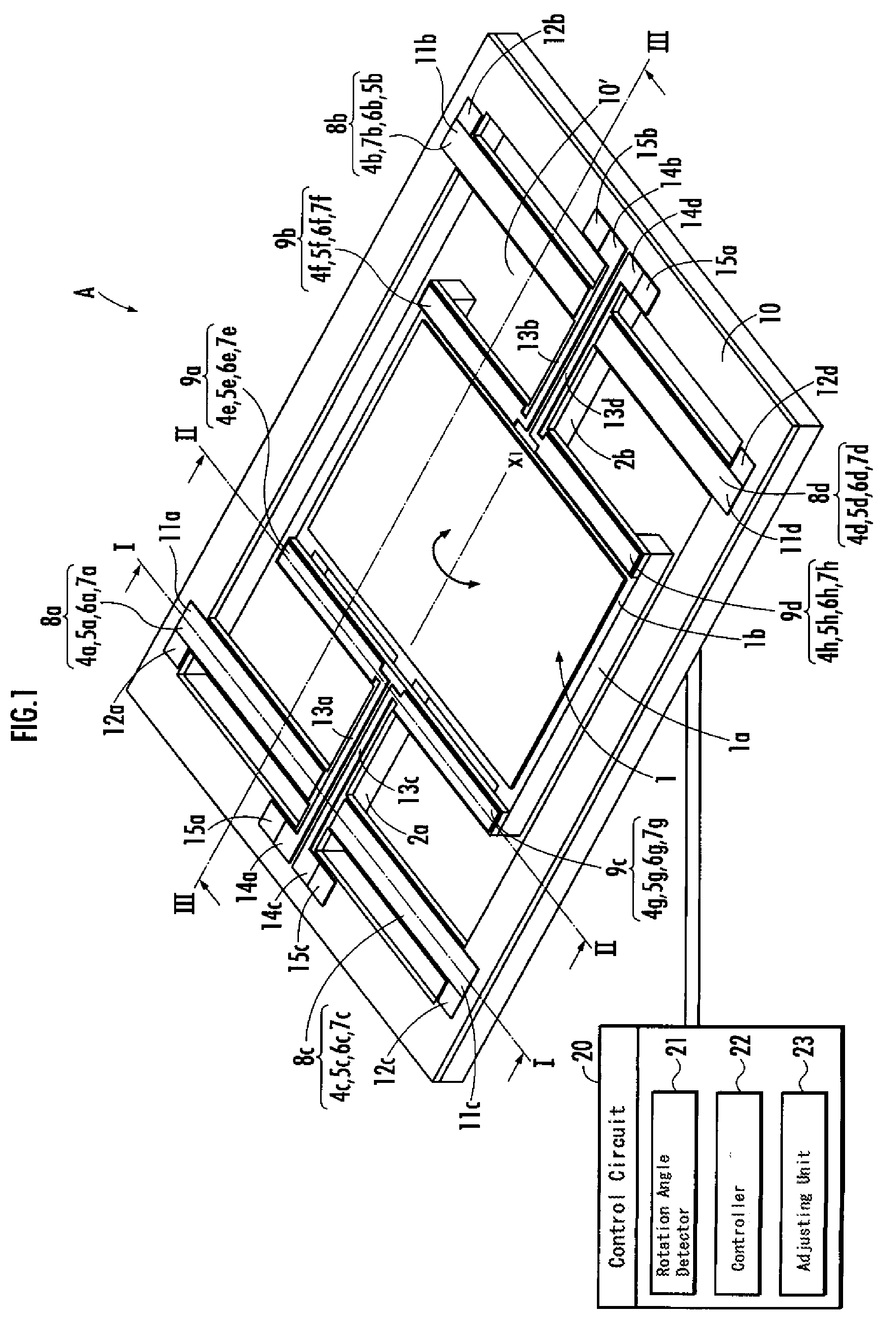
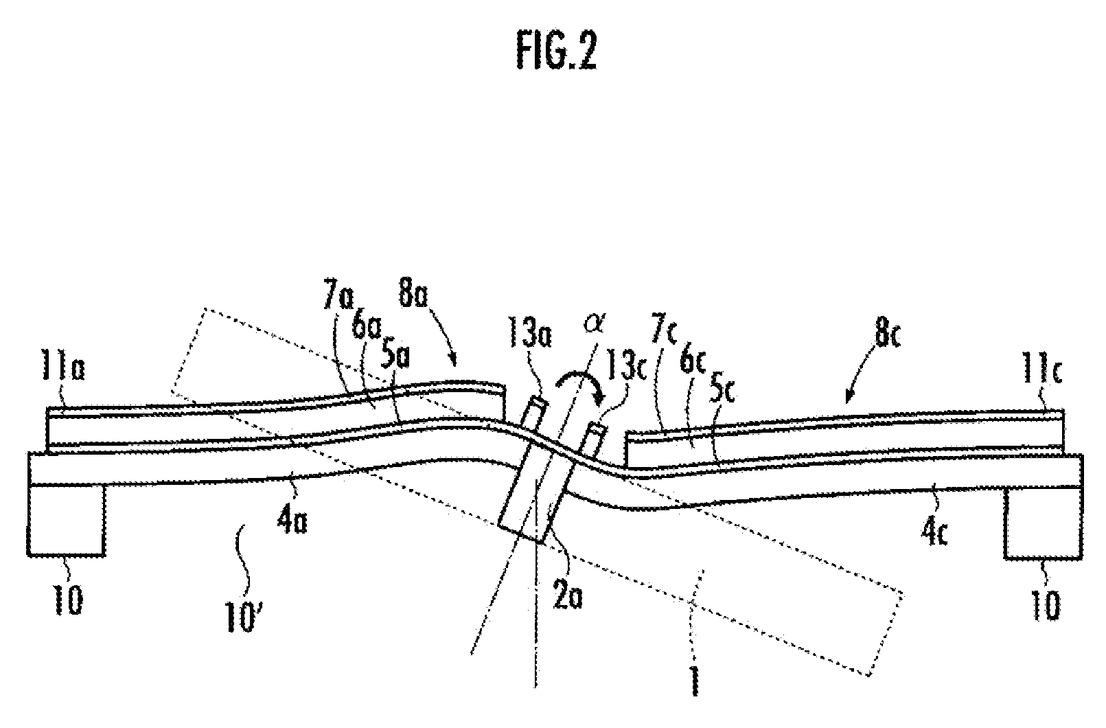
[0081]FIG. 1 schematically shows a configuration of an optical deflector according to the present embodiment. FIG. 2 is a drawing to explain the operation of the first piezoelectric element of the optical deflector of FIG. 1. FIG. 3 is a drawing to explain the operation of the second piezoelectric element of the optical deflector in FIG. 1. FIGS. 4A and 4B are graphs showing the detection of the rotation angle of the mirror in the optical deflector of FIG. 1. FIGS. 5A-5H illustrate a manufacturing process of the optical deflector of the present embodiment.

[0082]As shown in FIG. 1, the optical deflector A of the present embodiment includes a mirror 1, which reflects incoming light, torsion bars 2a, 2b, which are connected to the mirror 1, two pairs of the first piezoelectric elements 8a-8d, which drive the mirror 1 through the torsion bars 2a, 2b, resp...

second embodiment

[0129]With reference to FIGS. 6 and 7A-&B, an optical deflector according to a second embodiment of the present invention is described. FIG. 6 is a drawing to explain the operation of the second piezoelectric elements of the optical deflector of the second embodiment of the present invention. FIGS. 7A, 7B are graphs showing an adjustment of the rotation angle of the mirror in the optical deflector of FIG. 6. The structure of optical deflector A′ of the present embodiment may have the same configuration as the optical deflector of the first embodiment, but the operation is different. Alternatively, the present embodiment may have a structure different from the first embodiment to be more suited for the adjustment operation which will be described below.

[0130]In the optical deflector of the present embodiment, the second piezoelectric elements 9a-9d are used to assist and adjust the rotation of the mirror 1 caused by driving the first piezoelectric elements 8a-8d. The control circuit ...


PUM


Abstract

An optical deflector includes a mirror having a reflective plane; a torsion bar extending outwardly from an end of said mirror; a support surrounding said mirror; a first piezoelectric element, one end of said first piezoelectric element being connected to said torsion bar, the other end of the first piezoelectric element being connected to and supported by said support, said first piezoelectric element having at least one piezoelectric cantilever, the cantilever including a supporting body and a piezoelectric body formed on the supporting body to exhibit bending deformation due to piezoelectricity when a driving voltage is applied to the piezoelectric body, said piezoelectric element rotarily driving said mirror through said torsion bar when said driving voltage is applied; and a second piezoelectric element, one end of said second piezoelectric element being connected to said torsion bar, the other end of the second piezoelectric element being connected to and supported by said mirror.

Description

[0001]This application is a continuation-in-part of application Ser. No. 12 / 355,044, filed Jan. 16, 2009, which is hereby incorporated by reference in its entirety.BACKGROUND OF THE INVENTION[0002]1. Field of the Invention[0003]The present invention relates to an optical deflector for deflecting and sweeping a light beam such as a laser beam.[0004]2. Description of the Related Art[0005]Recently, as a MEMS (micro electro mechanical systems) device using semiconductor processes and the micro machining technology, an optical deflector has been proposed in which a mirror (a reflecting board) and electromechanical parts such as movable parts for the rotary drive of the mirror are formed integrally on a semiconductor substrate. In the optical deflector, in order to improve the deflection and sweeping performance further, it is desired that the drive status (e.g., the deflection angle and the deflection velocity) is controlled fast and precisely. For that purpose, the feedback control is r...

Claims


Application Information

Patent Timeline
Patent Type & Authority Applications(United States)
IPC IPC(8): G02B26/08
CPCG02B26/0858
Inventor TANI, MASANAOYASUDA, YOSHIAKIAKAMATSU, MASAHIROAIMONO, TAKANORI
Owner STANLEY ELECTRIC CO LTD
Why Eureka
Try Eureka