System and method for deploying self-expandable medical device with coating

Inactive Publication Date: 2009-07-23
BOSTON SCI SCIMED INC
View PDF3 Cites 15 Cited by
  • Summary
  • Abstract
  • Description
  • Claims
  • Application Information

AI Technical Summary

Benefits of technology

[0008]During loading and deployment of self-expandable stents, there may be significant friction between the stent surface and the sheath. Because the self-expandable stent has a tendency to want to expand to its relaxed state, the stent presses outward against the inner surface of the sheath. Thus, when the stent is being loaded into or deployed out of the sheath, the friction forces may be significant. Longer stents may have higher frictional forces. In the case of coated self-expandab

Problems solved by technology

During loading and deployment of self-expandable stents, there may be significant friction between the stent surface and the sheath.
Thus, when the stent is being loaded into or deployed out of the sheath, the friction forces may be significant.
In the case of coated self-expandable stents, these for

Method used


Image

  • System and method for deploying self-expandable medical device with coating
  • System and method for deploying self-expandable medical device with coating
  • System and method for deploying self-expandable medical device with coating

Examples


second embodiment

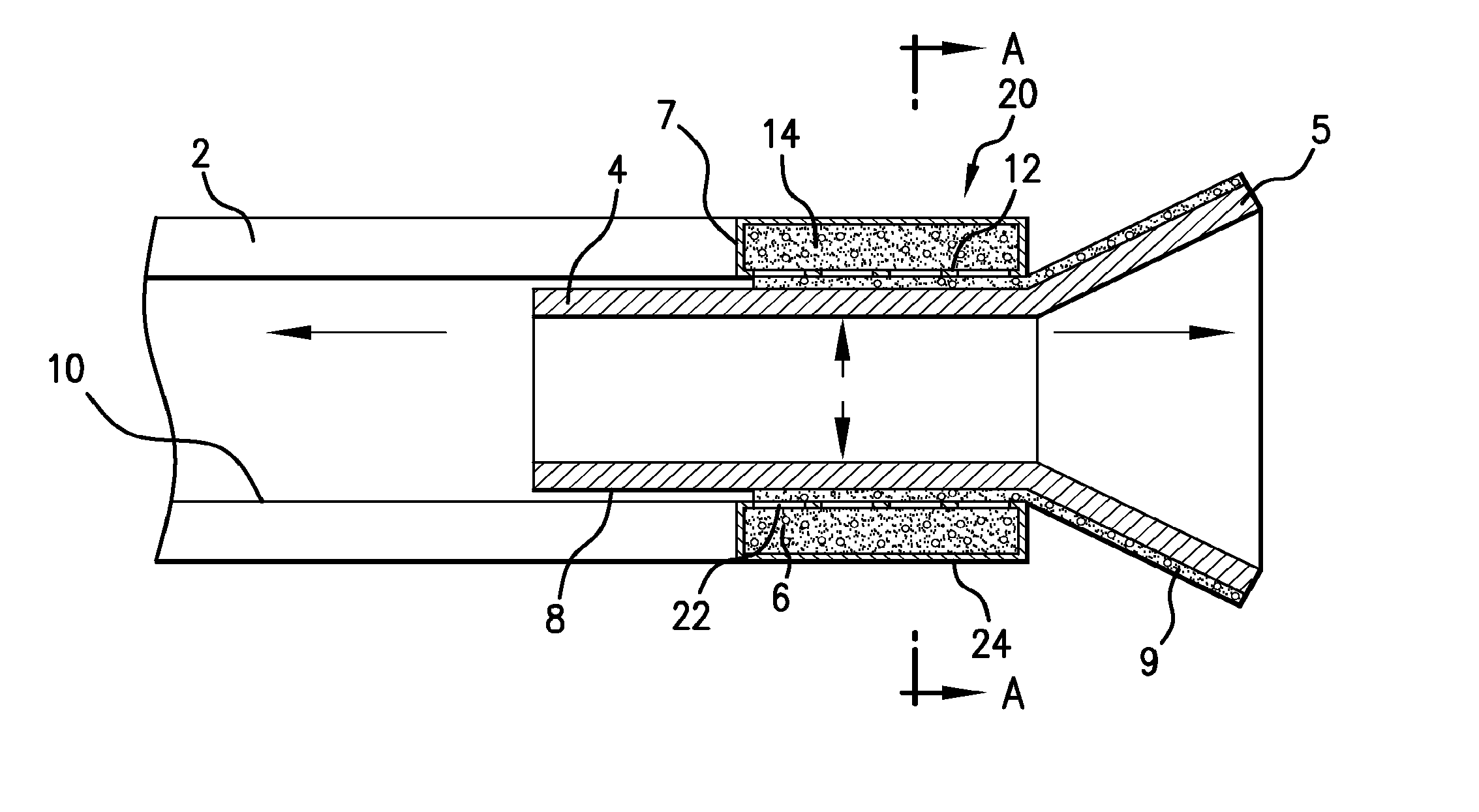
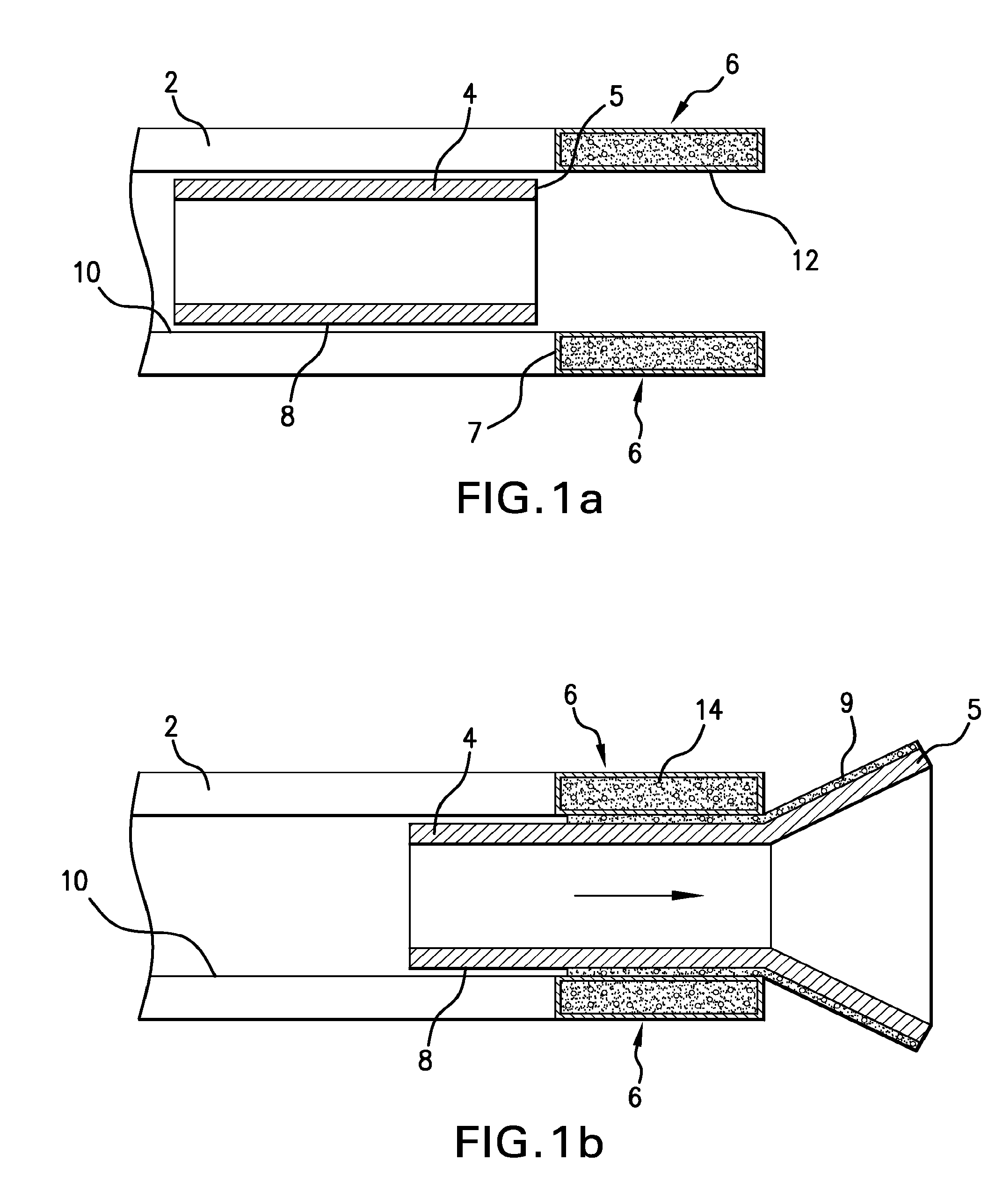
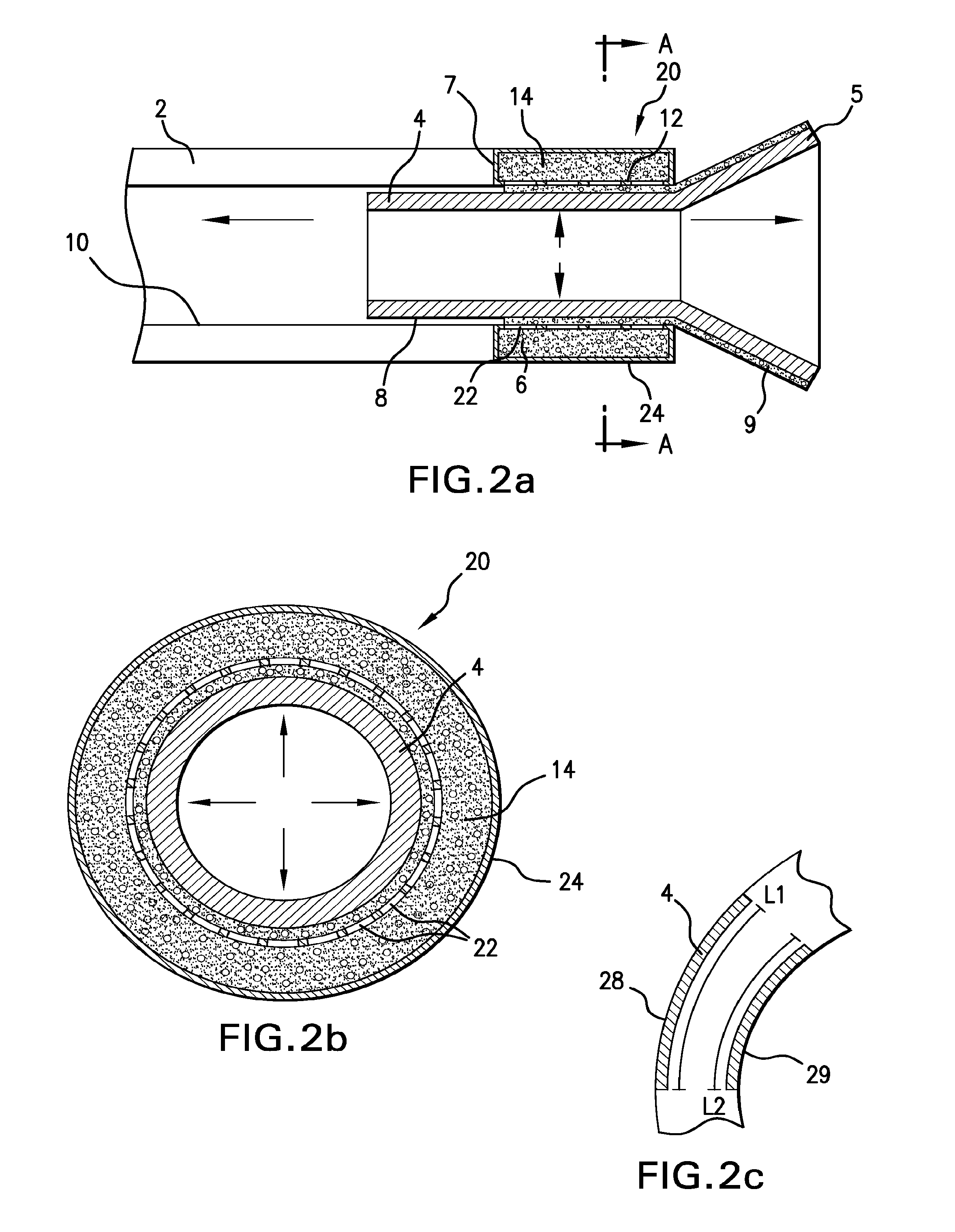
[0022]a coating applicator 6 containing a coating material 14 comprises a one or more ball assemblies 30, shown in FIGS. 3a, 3b, and 3c. Ball assemblies 30 somewhat resemble ball bearings and operate similar to a ballpoint pen. Each ball assembly 30 comprises a plurality of spherical balls 32, each having an outer surface 34, with the spherical balls 32 arranged around the circumference of coating applicator 6. Spherical balls 32 can be mounted within a modified ball bearing housing 36 that holds them in place but allows them to rotate. The spherical balls 32 are caused to rotate under the forces caused by the longitudinal movement of the stent 4 as it is deployed from the sheath 2.

[0023]The housing 36 can contain the coating material 14 within it. Alternatively, the top 38 of the housing 36 can be open to receive the coating material 14 from a separate reservoir. Alternatively, the top 38 of the housing 36 can have a sponge-like material to assist applying the coating material to t...

third embodiment

[0029]In the coating applicator 6, the entire coating applicator 6 is formed from a delivery medium 60, which in this example is a gel 62. The gel 62 can be any biocompatible substance with a high viscosity that will not react with the therapeutic agent 14, and may be, for example, silicone gel or oil. The gel 62 may be embedded with therapeutic agent 14, as shown in FIG. 4. As the stent 4 contacts the delivery medium 60, a portion of the gel 62 including the therapeutic agent 14 will rub off onto the outer surface 8 of the stent 4 due to the shear forces exerted. As the stent 4 is deployed, the medium 60 will be slowly depleted as it forms a coating 9 on the stent 4. The delivery medium can have varying amounts of therapeutic agent 14 in different areas of the gel 62, as shown in FIG. 4, to deliver more therapeutic agent 14 to a certain portion of the outer surface 8 of the stent 4. Alternatively, the gel 62 can have the therapeutic agent 14 evenly distributed throughout. Alternati...


PUM


Abstract

A system and method for providing a coating on a self-expandable medical device such as a stent are disclosed. The system comprises a coating applicator at the distal end of a sheath which delivers coating material onto the stent as the stent is deployed from the sheath. Thus, the stent may be loaded into the sheath without a coating on the stent, thereby avoiding shearing off or damaging the coating during loading. Also, the coating is applied only as the stent exits the sheath, thereby avoiding shearing off or damaging the coating during deployment.

Description

CROSS REFERENCE TO RELATED APPLICATION[0001]The present application claims priority to U.S. provisional application Ser. No. 61 / 021,801 filed Jan. 17, 2008, the disclosure of which is incorporated herein by reference in its entirety.FIELD OF INVENTION[0002]The present invention provides methods and materials for providing a coating on a medical device.BACKGROUND[0003]Medical devices may be coated so that the surfaces of such devices have desired properties or effects. For example, it may be useful to coat medical devices to provide for the localized delivery of therapeutic agents to target locations within the body, such as to treat localized disease (e.g., heart disease) or occluded body lumens. Localized drug delivery may avoid some of the problems of systemic drug administration, which may be accompanied by unwanted effects on parts of the body which are not to be treated. Additionally, treatment of the afflicted part of the body may require a high concentration of therapeutic ag...

Claims


Application Information

Patent Timeline
IPC IPC(8): A61F2/84
CPCA61F2/95A61F2250/0067B05C1/022B05C1/06B05C1/08
Inventor WEBER, JANSEIDEL, DOMINIQUE
Owner BOSTON SCI SCIMED INC
Why Eureka
Try Eureka