Dry friction material and method for manufacturing the same

Inactive Publication Date: 2013-07-18
AISIN CHEM CO LTD
View PDF2 Cites 4 Cited by
  • Summary
  • Abstract
  • Description
  • Claims
  • Application Information

AI Technical Summary

Benefits of technology

The patent relates to a dry friction material that has improved processing and mechanical characteristics. The material has a fixed part with a higher content of glass fibers or compounded rubber, which enhances strength and stiffness, making it easier to hole bore. The content of the glass fibers or compounded rubber can be adjusted at any position, such as the fixed part or other parts of the material. This allows for a unique mechanical characteristic, such as friction force, for each part attached to the core material. Additionally, the material can have a higher coefficient of static friction for stable attachment to the core material and can slide in relation to a counter material. The material also has grooves for more secure attachment to the core material.

Problems solved by technology

However, in the techniques described in the patent document 1, if sealing of a case containing the dry friction material is insufficient, outside muddy water, rain water or the like penetrates through a gap and is absorbed into glass fibers exposed on a friction surface by a top surface polishing.
In addition, if slide with a friction counter material is not performed for a long period of time in this state, there sometimes occurs a situation where absorbed water causes rust on a steel plate as the friction counter material and where rusting with the friction counter material is generated.

Method used


Image

  • Dry friction material and method for manufacturing the same
  • Dry friction material and method for manufacturing the same
  • Dry friction material and method for manufacturing the same

Examples


first embodiment

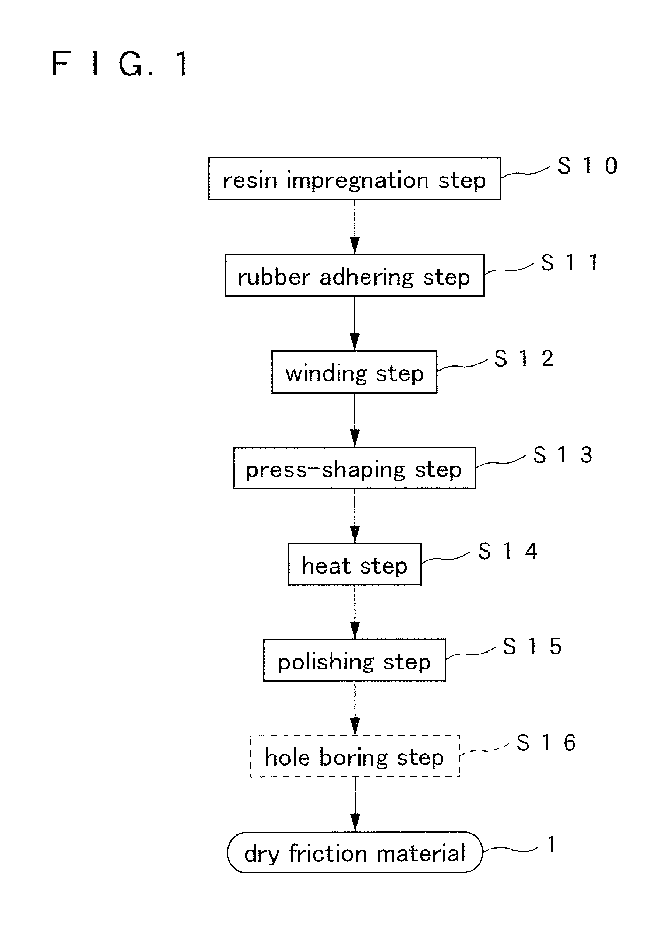
[0087]Next, a more specific manufacturing step of a dry friction material according to the first embodiment of the present invention is described referring to FIG. 2.

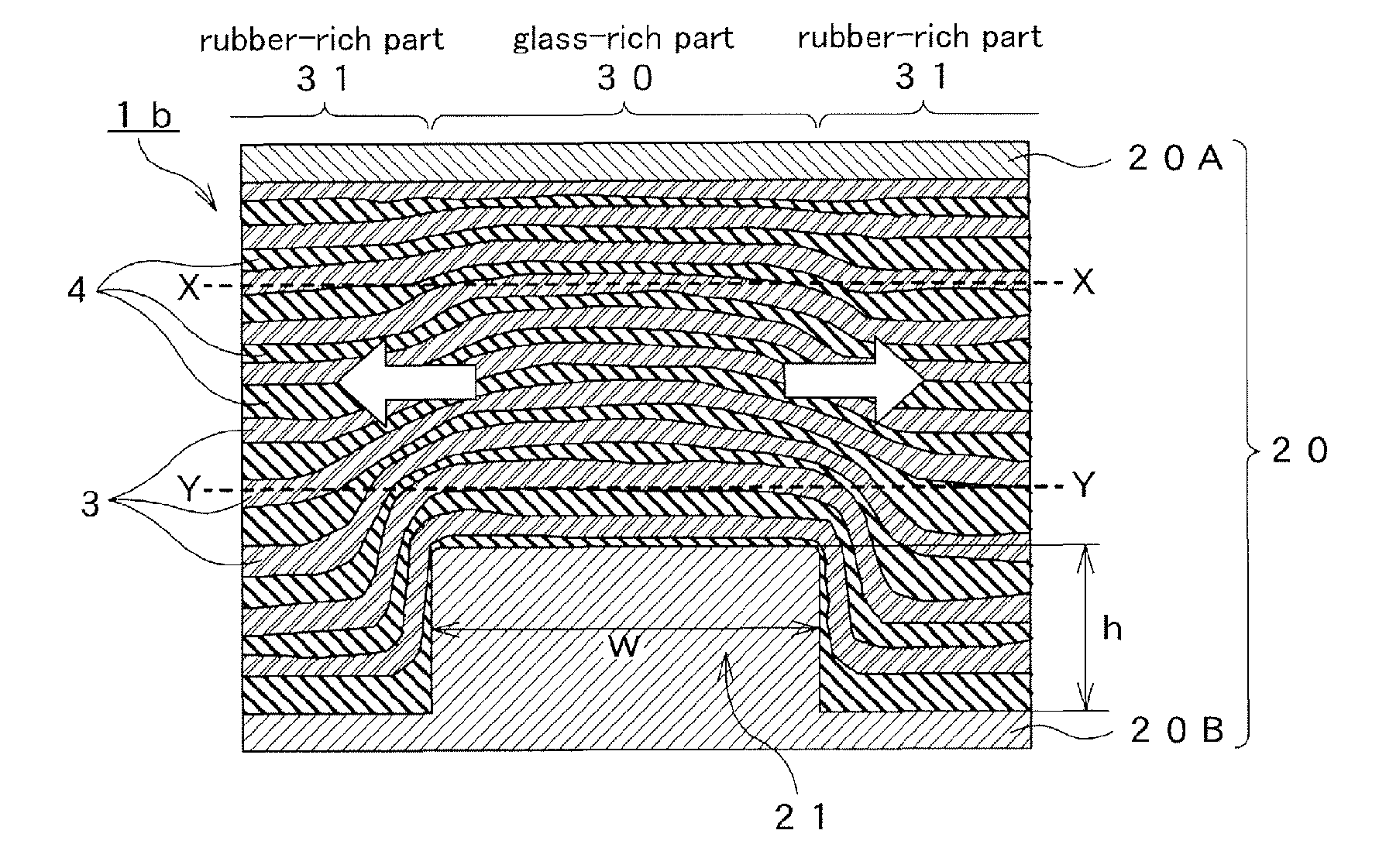
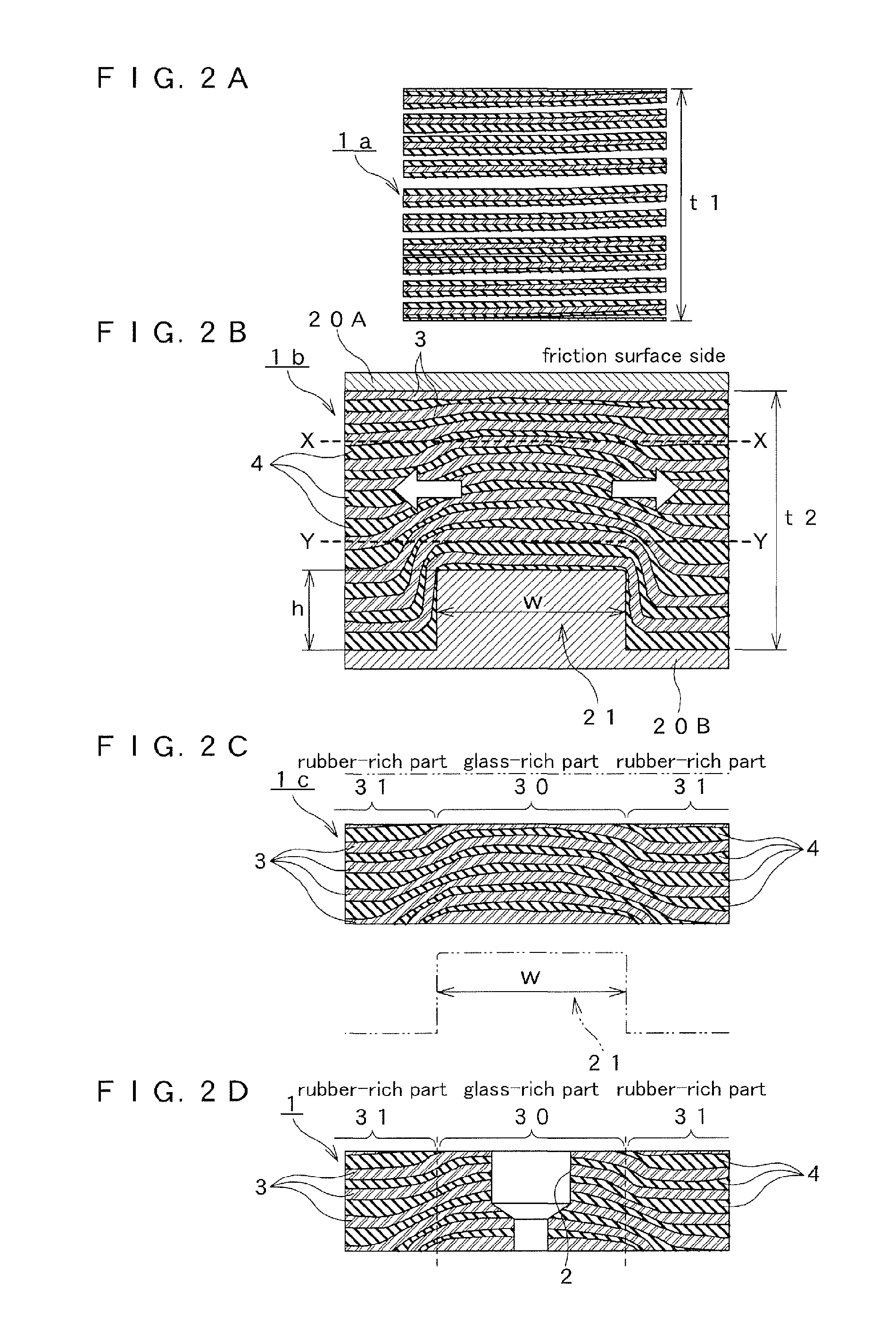
[0088]As shown in FIG. 2A, in the manufacturing steps of the dry friction material 1 according to the first embodiment, a wound product la as a preliminary shaped product manufactured in the winding step (STEP S12 of FIG. 1) as the preliminary shaping step has a thickness of t1. t1 is generally within a range of about 5 mm to 15 mm. As shown in FIG. 2B, the wound product la is pushed in a shaping die, to be more precise, a lower die 20A and an upper die 20B of a press die 20 to be press-shaped in the press-shaping step (STEP S13 of FIG. 1), so that it is formed into a shaped body 1b having a thickness of t2 (t1>t2).

[0089]At this time, a rib 21 of the upper die 20B of the press die is provided so as to protrude toward a shaped body side (friction surface side) on an opposite surface (rear surface) in relation to a fricti...

second embodiment

[0101]As shown in FIG. 5A, a wound product la manufactured in a winding step corresponding to STEP S12 of FIG. 1 in manufacturing steps of a dry friction material 1 according to a second embodiment of the present invention has a thickness of t1 as in the first embodiment. The wound product 1a is press-shaped by pushing an upper die 20B in a lower die 20A of a press die 20 in a press-shaping step corresponding to STEP S13 of FIG. 1 to be formed into a shaped body 1b having a thickness of t2 (t1>t2), as shown in FIG. 5B.

[0102]At this time, a rib 21 of the upper die 20B of the press die 20 is provided so as to protrude toward a shaped body side (friction surface side) on an opposite surface (rear surface) in relation to a friction surface side of a glass-rich part 30 that is a bored part of the press die to be subjected to the hole boring. The rib 21 has a fan-shape of substantially a rectangular parallelepiped shape made into a shape having a predetermined angle to the center of the d...

third embodiment

[0109]The above-described first and second embodiments were described on the assumption that the bored hole 2 was provided on the glass-rich part 30. However, in the practice of the present invention, it is possible to omit the bored hole 2 on the glass-rich part 30 to the fixing to the core material 5, since, as described in the second embodiment, the rubber-rich part 31 has a high friction resistance with the core material 5 and such rubber-rich part 31 makes it hard to give stress to the glass-rich part 30.

[0110]FIG. 6 is the same third embodiment and a basic structure thereof is the same as the second embodiment. In particular, FIG. 6A and FIG. 6B of the present embodiment are basically not different from FIG. 5A and FIG. 5B of the second embodiment.

[0111]As shown in FIG. 6C, a shaped body 1c of the present embodiment is formed into a polished body 1c having a flat ring shape or a dry friction material 1 by polishing both top and rear sides thereof in a polishing step correspond...


PUM

PropertyMeasurementUnit
Fractionaaaaaaaaaa
Fractionaaaaaaaaaa
Percent by massaaaaaaaaaa

Abstract

In a dry friction material and a method for manufacturing the same, to maintain a content of glass fibers low on a whole dry friction material to apply a hole boring for caulking assembly with high strength and high stiffness at a part to be subjected to the hole boring.A part (glass-rich part 30) to be subjected to the hole boring is pressed at a higher pressure than a part not to be subjected to the hole boring in a press-shaping step by providing a rib 21 protruding toward a shaped body side on a part of press dies 20A, 20B corresponding to the part to be subjected to the hole boring. Thereby, only a compounded rubber 4 is pushed outward and only the glass-rich part 30 has an increase in a content of glass fibers 3. Thereby, strength that can withstand the hole boring is obtained. Accordingly, a dry friction material 1 with a bored hole 2 bored without generating a failure in the hole boring can be manufactured.

Description

TECHNICAL FIELD[0001]This invention relates to a dry-type friction material, for example, a dry friction material that constitutes a torque limiter clutch, a slip clutch, a thrust damper or the like for use in an automobile or the like and a method for manufacturing the same.BACKGROUND ART[0002]In a system including a dry friction material such as clutch facing, a damper, and a torque limiter or the like, a method is known as a method for manufacturing a dry friction material, as shown in a patent document 1. It comprises a resin impregnation step for impregnating a fiber bundle (glass roving) made by bundling long glass fibers to be a base material with an impregnation liquid containing a thermosetting resin to form a resin-impregnated string, and a rubber adhering step for adhering a compounded rubber to the resin-impregnated string. Here, it is known that a medium of the impregnation liquid is water and that the thermosetting resin is an aqueous melamine-modified phenolic resin w...

Claims


Application Information

Patent Timeline
IPC IPC(8): F16D69/02
CPCF16D13/64F16D69/00F16D69/026Y10T428/213F16D2200/0065F16D2300/10F16D2069/004
Inventor IWAMA, KIYOSHIONO, HIDEOMORITA, KAZUYA
Owner AISIN CHEM CO LTD
Why Eureka
Try Eureka