Crack growth evaluation apparatus, crack growth evaluation method, and recording medium recording crack growth evaluation program

US20090187353A1Active Publication Date: 2009-07-23FUJITSU LTD

Image

  • Crack growth evaluation apparatus, crack growth evaluation method, and recording medium recording crack growth evaluation program
  • Crack growth evaluation apparatus, crack growth evaluation method, and recording medium recording crack growth evaluation program
  • Crack growth evaluation apparatus, crack growth evaluation method, and recording medium recording crack growth evaluation program

Examples


Embodiment Construction

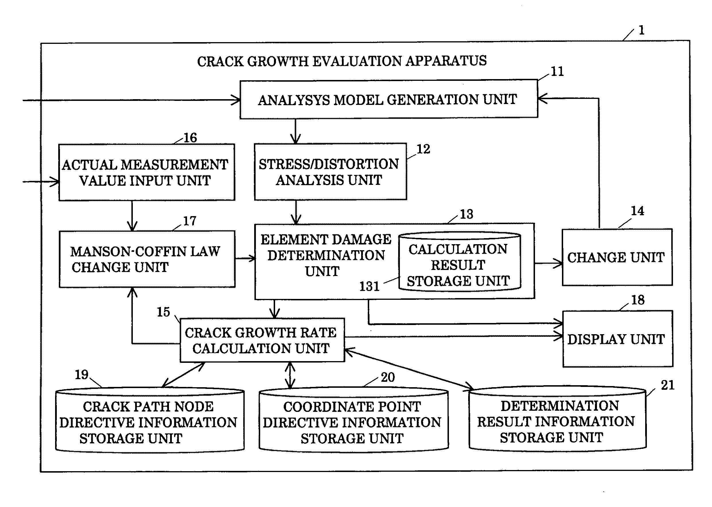
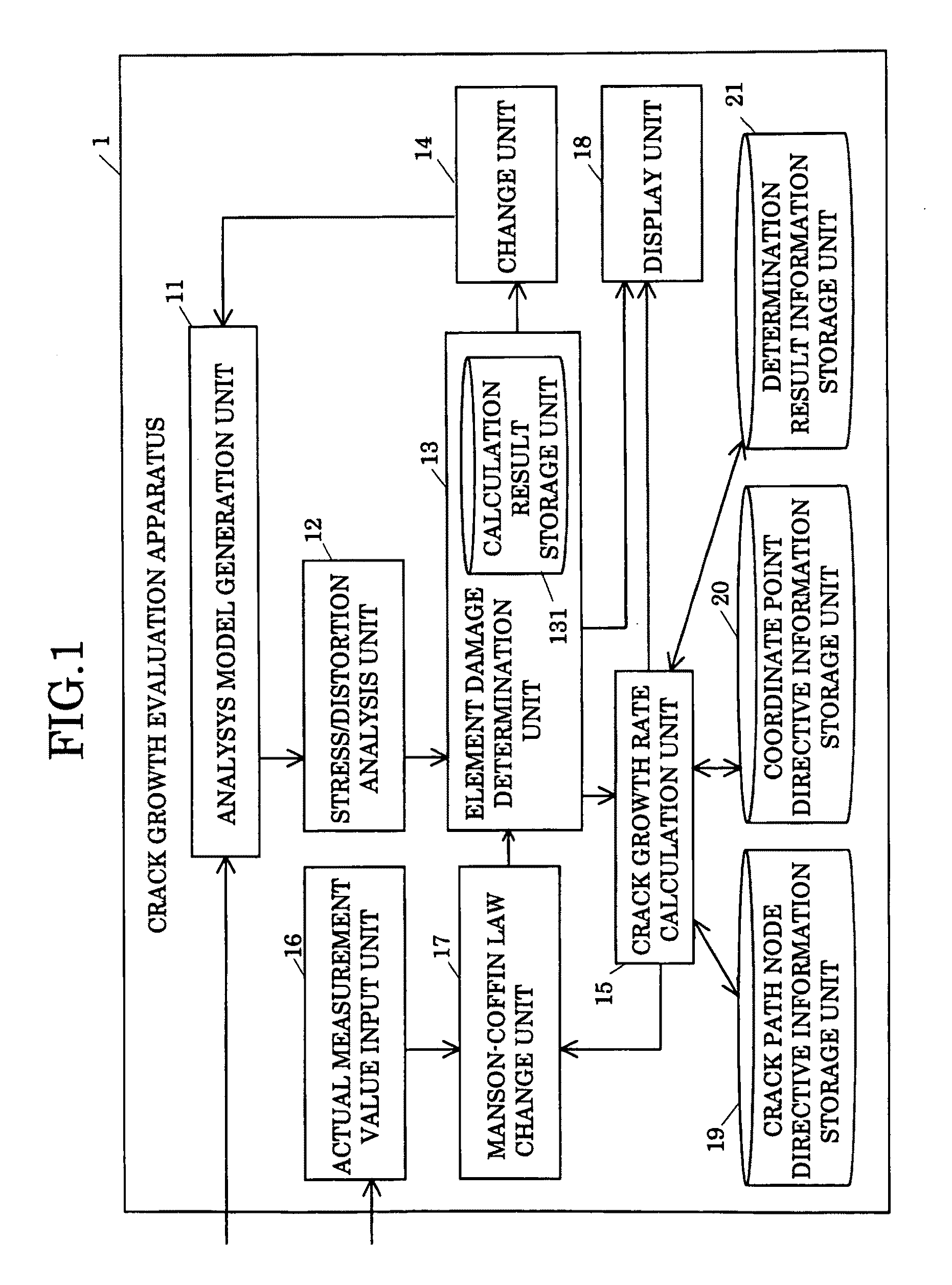
[0045]FIG. 1 is a diagram showing an example of a structure of a crack growth evaluation apparatus of the present embodiment.

[0046]A crack growth evaluation apparatus 1 is a computer that evaluates a growth of a crack occurring in a continuum. The crack growth evaluation apparatus 1 includes an analysis model generation unit 11, a stress / distortion analysis unit 12, an element damage determination unit 13, a change unit 14, a crack growth rate calculation unit (hereinafter referred to as a calculation unit) 15, an actual measurement value input unit 16, a Manson-Coffin law change unit 17, a display unit 18, a crack path node directive information storage unit 19, a coordinate point directive information storage unit 20, and a determination result information storage unit 21. Each unit provided for the crack growth evaluation apparatus 1 is realized by a CPU and a program present in main memory and executed on the CPU.

[0047]The analysis model generation unit (hereinafter referred to ...


PUM


Abstract

An element damage determination unit calculates a cumulative value of a damage value using a Manson-Coffin law for a plurality of finite elements of a continuum based on a result of a stress / distortion analyzing process, and determines whether or not the cumulative value of the damage value is equal to or exceeds a threshold. A calculation unit obtains first correspondence information indicating the correspondence between the number of cycles of a load and a growth rate of a crack occurring in the continuum based on the determination result. A Manson-Coffin law change unit changes a Manson-Coffin law based on the first correspondence information and second correspondence information indicating the correspondence between an actual measurement value of the number of cycles of a load applied to the continuum and an actual measurement value of the growth rate of a crack occurring in the continuum at that time.

Description

CROSS-REFERENCE TO RELATED APPLICATIONS[0001]This application claims the conventional priority based on Japanese Application No. 2008-012272, filed on Jan. 23, 2008, the disclosures of which are incorporated herein by reference.BACKGROUND OF THE INVENTION[0002]1. Field of the Invention[0003]The present invention relates to a crack growth evaluation apparatus, a crack growth evaluation method, and a recording medium recording a crack growth evaluation program. More specifically, the present invention relate to a crack growth evaluation apparatus, a crack growth evaluation method, and a recording medium recording a crack growth evaluation program capable of evaluating with high accuracy the growth of a crack occurring in a continuum in a finite element method.[0004]2. Description of the Related Art[0005]For a solder material and various types of joining resin material (adhesive), stable connection reliability of a junction is important. Practically, it is necessary for a connected por...

Claims


Application Information

Patent Timeline
23 Jul 2009
Publication
US20090187353A1
IPC
G01N19/08
CPC
G01N3/32; G01N2203/0016; G01N2203/0224; G01N2203/0066; G01N2203/006
Inventors
SAKAI, HIDEHISA; MORIMUNE, KATSUFUMI