This helps you quickly interpret patents by identifying the three key elements:
Problems solved by technology
Method used
Benefits of technology
Benefits of technology
[0011]In the above described background technology, each horizontal period for scanning the lines is short when the resolution of the panel is high, or in the case of high frame rate driving, where the speed of rewrite of screens is as high as 120 Hz or higher, which is effective for reducing blurring in moving images, and when a sufficient write-in period during which the voltage corresponding to display data is applied to pixel electrodes cannot be secured, a desired voltage cannot be written into pixel electrodes, and there is a risk that the image quality might lower.
[0012]An object of the present invention is to provide a display device with high frame rate drive and high resolution, as well as a method where a sufficient period for the writing in of a display signal into pixels can be secured.
[0015]According to the present invention, a sufficient write-in period during which a target display signal is provided to pixel electrodes can be secured in liquid crystal displays with a high frame rate drive of 120 Hz or higher, which is effective in order to reduce blurring of moving images, and with high resolution, and thus, the image quality can be prevented from lowering.
Problems solved by technology
In the above described background technology, each horizontal period for scanning the lines is short when the resolution of the panel is high, or in the case of high frame rate driving, where the speed of rewrite of screens is as high as 120 Hz or higher, which is effective for reducing blurring in moving images, and when a sufficient write-in period during which the voltage corresponding to display data is applied to pixel electrodes cannot be secured, a desired voltage cannot be written into pixel electrodes, and there is a risk that the image quality might lower.
Method used
Image
Click on the blue label to locate the original text in one second.
Reading with bidirectional positioning of images and text.
Examples
first embodiment
[0040]The active matrix type liquid crystal display device and driving method according to the present invention are described in reference to FIGS. 1 to 5.
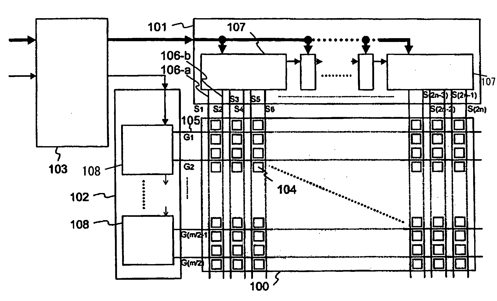
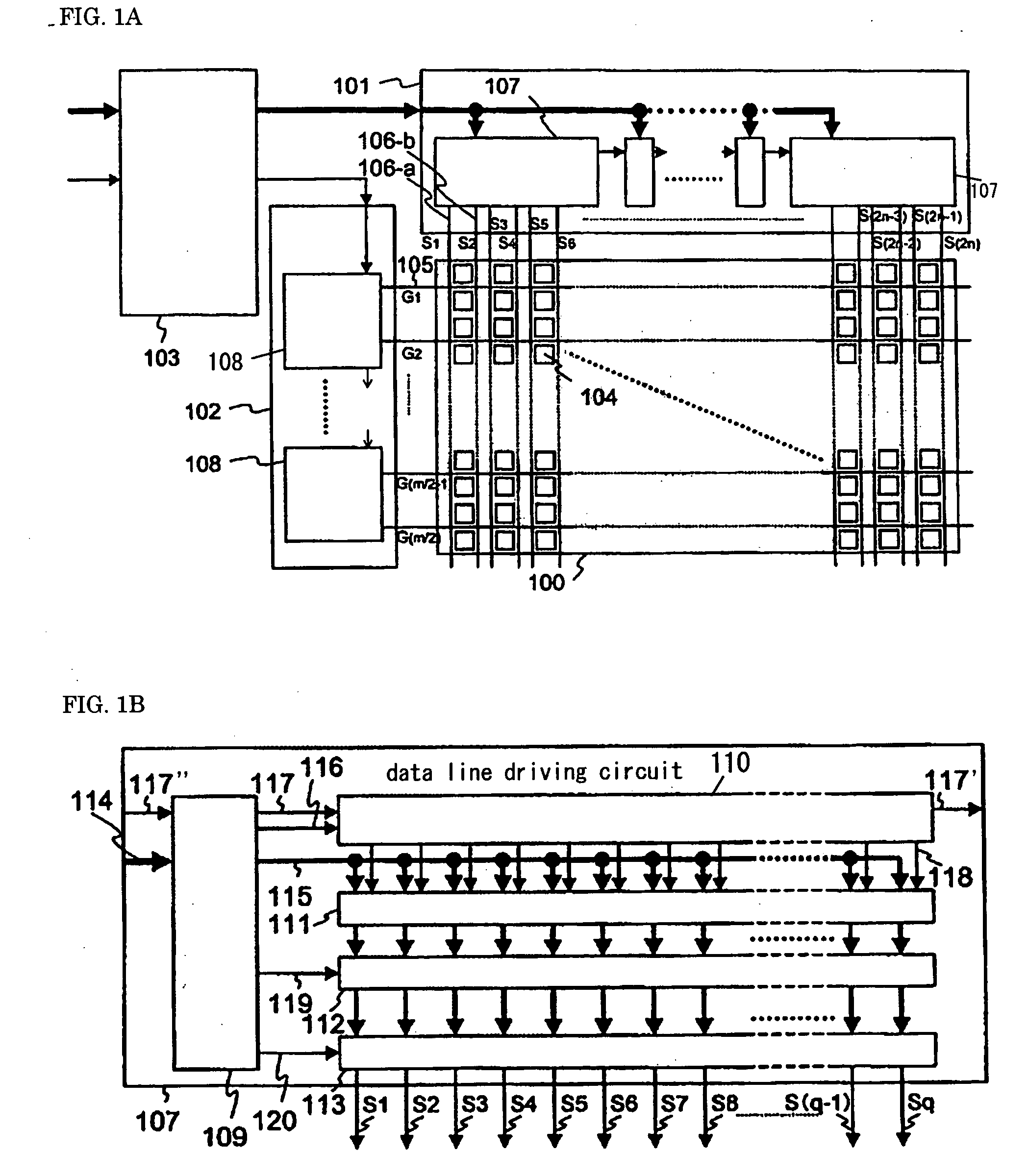
[0041]FIG. 1(a) is an example of a diagram showing the block configuration of the liquid crystal display device according to the first embodiment of the present invention.
[0042]The liquid crystal display device according to the first embodiment is formed of a liquid crystal panel portion 100, a data line driving portion 101, a gate line driving portion 102 and a timing controlling portion 103. The liquid crystal panel portion 100 is provided with active elements, such as TFT's, as liquid crystal pixels 104 provided in a matrix of n×m in a plane.
[0043]FIG. 2 shows the details of the alignment of pixels. Red (R) pixels, green (G) pixels and blue (B) pixels are respectively aligned in vertical stripes. The electrodes for turning ON / OFF each active element 200 are connected to one gate line 105 shared by pixel groups in two horizonta...
second embodiment
[0053]The active matrix type liquid crystal display device and the driving method according to the present invention are described in reference to FIGS. 1 and 7 to 9.
[0054]The configuration of the second embodiment is the same as that of the first embodiment, and is the configuration shown in FIG. 1(a), which is formed of a liquid crystal panel portion 100, a data line driving portion 101, a gate line driving portion 102 and a timing controlling portion 103. The liquid crystal panel portion 100 is provided with active elements, such as TFT's, as liquid crystal pixels 104 arranged in a matrix of n×m in a plane. The difference between the first embodiment and the second embodiment is in the connection between the TFT's of the pixels and the data lines.
[0055]FIG. 7 shows the alignment of pixels in the second embodiment in detail. Pixels in the first line (704-1, 704-3, 704-5, 704-7 . . . ) are connected to odd data lines (704-1 is connected to the data line S1, 704-3 is connected to th...
third embodiment
[0061]The active matrix type liquid crystal display device and driving method according to the present invention are described in reference to FIGS. 1, 10 and 11.
[0062]The configuration of the third embodiment is the same as that of the first embodiment, which is shown in FIG. 1(a) and formed of a liquid crystal panel portion 100, a data line driving portion 101, a gate line driving portion 102 and a timing controlling portion 103. The liquid crystal panel portion 100 is provided with active elements, such as TFT's, as liquid crystal pixels 104 arranged in a matrix of n×m in a plane. In the third embodiment, the panel corresponds to display data for expressing RGBW, where white (W) is added in order to increase the efficiency of the brightness, unlike in display data expressed with the three primary colors of light: red (R), green (G) and blue (B), in the first and second embodiments. Here, the fourth pixels are not limited to white.
[0063]FIG. 10 shows an example of a panel with RGB...
PUM
Abstract
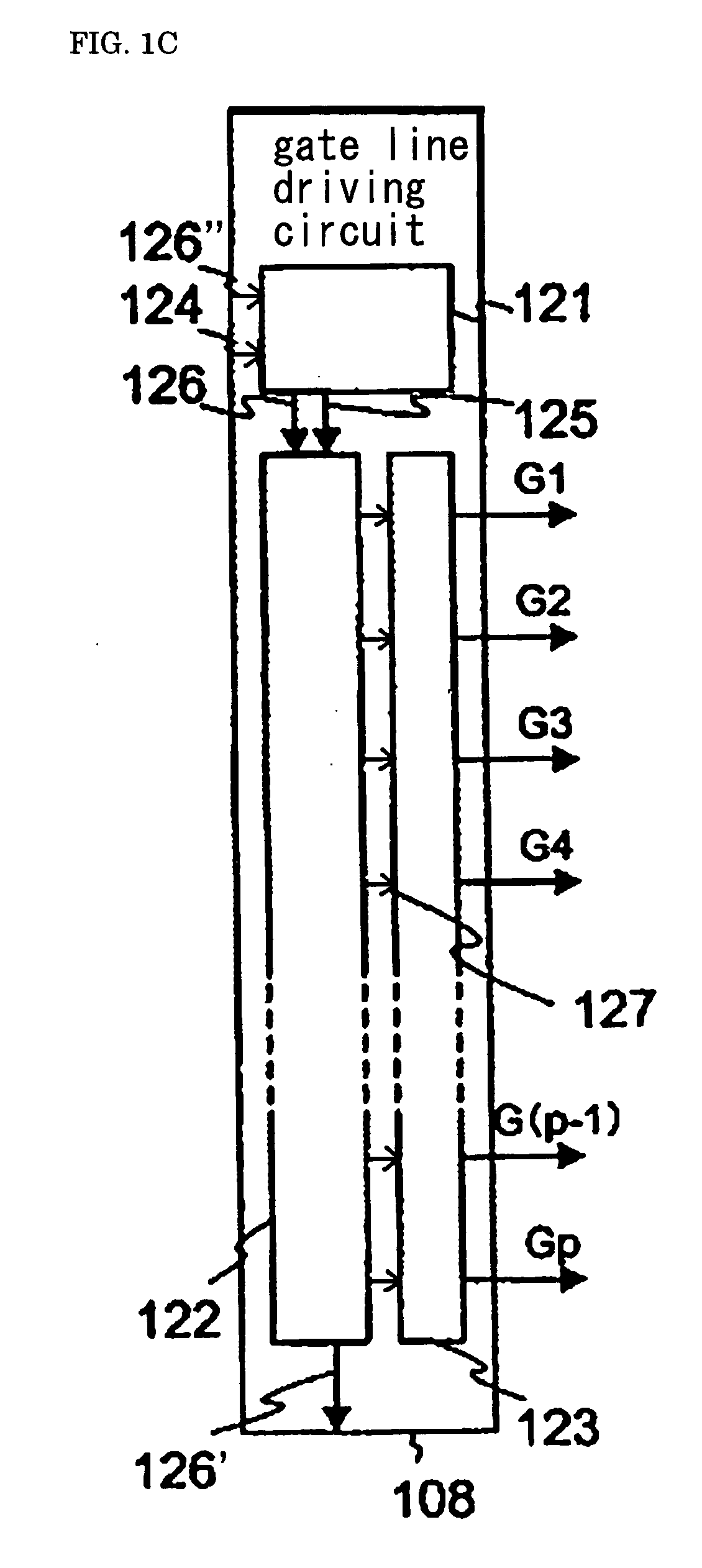
In the case where one horizontal period becomes shorter as a high frame rate drive of 120 Hz or higher is introduced or the resolution is increased, the time for the writing in of a voltage to the holding capacitor of pixels cannot be sufficiently secured.Two data lines are provided to an electrode for supplying a data voltage to a group of pixels in the vertical direction in such a manner that one data line of the two data lines is connected to one of the two pixels in the vertical direction and the other data line of the two data lines is connected to the other pixel, while one gate line shared by two horizontal lines formed of two pixels, to which different data lines adjacent in the vertical direction are connected, is provided and connected to the electrode for controlling the turning ON / OFF, the data line driving portion has outputs of which the number is two times greater than the number of horizontal pixels in order to make it possible to apply a voltage simultaneously to the pixels for two horizontal lines, and the gate line driving portion has outputs of which the number if ½ the number of vertical pixels by connecting one gate line to two horizontal lines.
Description
BACKGROUND OF THE INVENTION[0001]The present invention relates to an active matrix type display device and a method for driving the same, and in particular, to a liquid crystal display or the like.[0002]Active matrix type liquid crystal display devices are characterized by being thin and highly precise and having low power consumption, and thus, used as display devices for thin televisions and the like.[0003]FIG. 16(a) shows an example of the configuration of a conventional liquid crystaldisplay device. The conventional liquid crystal display device is formed of a liquid crystal panel 1600, a data line driving portion 1601, a gate line driving portion 1602 and a timing controlling portion 1603. The liquid crystal panel 1600 is provided with active elements, such as thin film transistors (hereinafter referred to as TFT's) in pixels 1604 which are aligned in a matrix of n×m in a plane. FIG. 17 is a diagram showing the alignment of the pixels 1604 in detail. Electrodes for controlling...
Claims
Application Information
Patent Timeline
Application Date:The date an application was filed.
Publication Date:The date a patent or application was officially published.
First Publication Date:The earliest publication date of a patent with the same application number.
Issue Date:Publication date of the patent grant document.
PCT Entry Date:The Entry date of PCT National Phase.
Estimated Expiry Date:The statutory expiry date of a patent right according to the Patent Law, and it is the longest term of protection that the patent right can achieve without the termination of the patent right due to other reasons(Term extension factor has been taken into account ).
Invalid Date:Actual expiry date is based on effective date or publication date of legal transaction data of invalid patent.

