

Light guiding body, substrate for display device, and display device
a technology of display device and substrate, which is applied in the direction of lighting and heating apparatus, instruments, mechanical equipment, etc., can solve the problems of low light use efficiency of conventional liquid crystal display device and waste of portion of light incident in such regions, and achieve the effect of higher light use efficiency
- Summary
- Abstract
- Description
- Claims
- Application Information
AI Technical Summary
Benefits of technology
Problems solved by technology
Method used
Image

Examples
embodiment 1
Preferred Embodiment 1
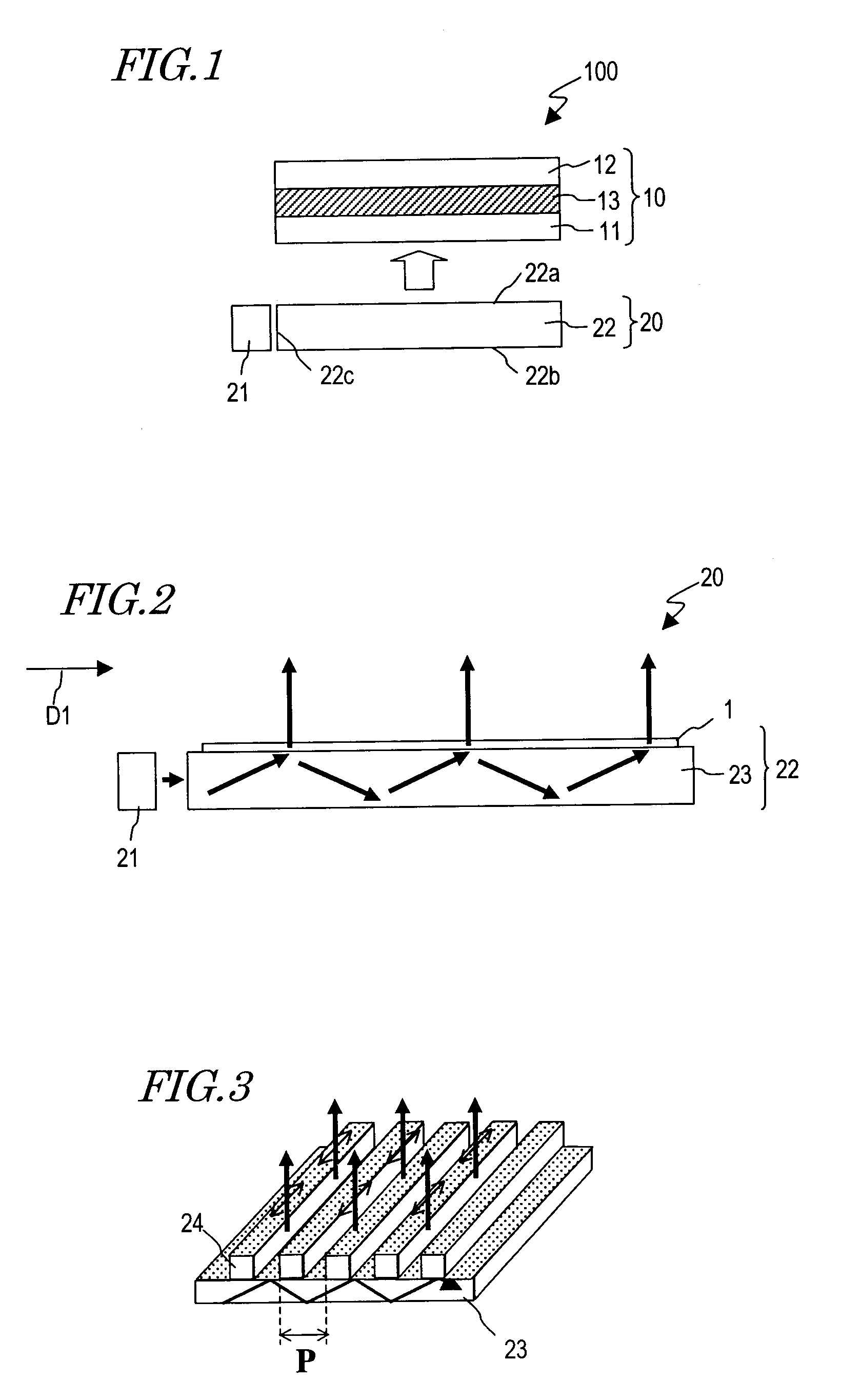
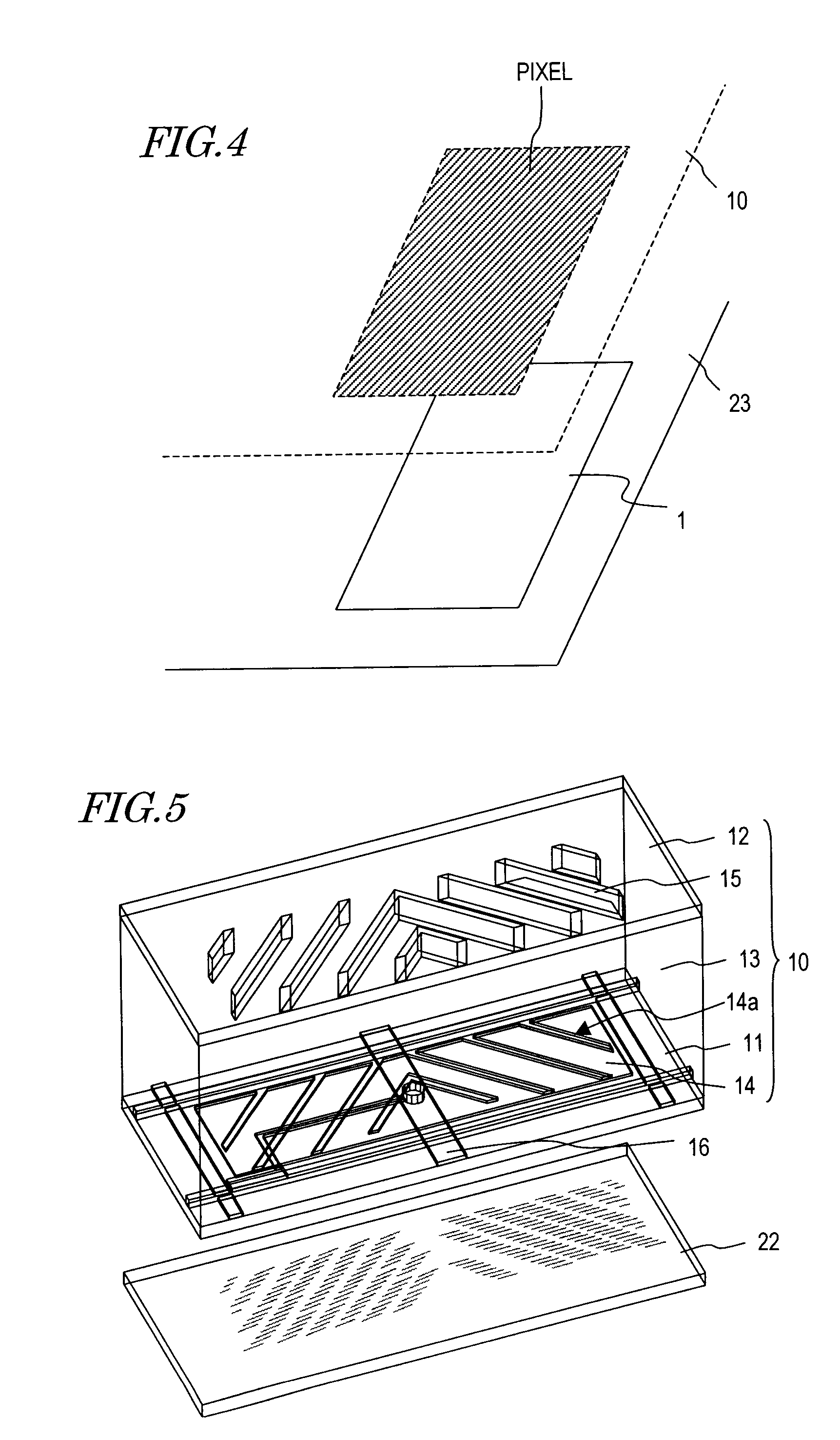
[0096]FIG. 1 shows a liquid crystal display device 100 of this preferred embodiment. The liquid crystal display device 100 includes a liquid crystal display panel 10 having a plurality of pixels and an illuminator 20 placed on the back side of the liquid crystal display panel 10.
[0097]The liquid crystal display panel 10 includes a pair of substrates 11 and 12 and a liquid crystal layer 13 interposed therebetween, to perform display using light emerging from the illuminator 20. The liquid crystal display panel 10 can adopts a variety of known display modes such as a twisted nematic (TN) mode, an electrically controlled birefringence (ECB) mode, a multi-domain vertical alignment (MVA) mode and a continuous pinwheel alignment (CPA) mode.
[0098]The illuminator 20 has a light source 21 and a light guide 22 for guiding light emitted from the light source 21 in a predetermined direction. The light source 21 may be a light emitting diode (LED) and a cold-cathode tube, f...
embodiment 2
Preferred Embodiment 2
[0160]FIG. 26 shows a liquid crystal display device 200 of this preferred embodiment. The liquid crystal display device 200 includes a liquid crystal display panel 10 having a plurality of pixels and an illuminator 20′ placed on the back side of the liquid crystal display panel 10.
[0161]While the illuminator 20 of the liquid crystal display device 100 of Preferred Embodiment 1 has the light source 21 at a side of the light guide 22, the illuminator 20′ of the liquid crystal display device 200 of this preferred embodiment has a light source 21 below a light guide 22. That is, while the side plane 22c of the light guide 22 functions as the plane of incidence in the illuminator 20 in Preferred Embodiment 1, the back plane 22b of the light guide 22 functions as the plane of incidence in the illuminator 20′ in this preferred embodiment.
[0162]Hereinafter, the illuminator 20′ will be described in more detail with reference to FIG. 27. As shown in FIG. 27, the light gu...
embodiment 3
Preferred Embodiment 3
[0169]FIG. 28 shows a liquid crystal display device 300 of this preferred embodiment. The liquid crystal display device 300 has no illuminator, unlike the liquid crystal display devices 100 and 200 of Preferred Embodiments 1 and 2.
[0170]The liquid crystal display device 300 has a pair of substrates 11 and 12 and a liquid crystal layer 13 as a light modulation layer interposed between these substrates. As used herein, the substrate 11 placed on the back side of the liquid crystal layer 13 (opposite to the observer side) is called a “back substrate”, and the substrate 12 placed on the front side of the liquid crystal layer 13 (observer side) is called a “front substrate”. The back substrate 11 is an active matrix substrate, for example, and the front substrate 12 is a color filter substrate, for example.
[0171]The back substrate 11 has a principal plane (facing the liquid crystal layer 13) and a back plane opposing to each other and a plurality of side planes loca...
PUM
 Abstract
Description
Claims
Application Information