Acoustic transducer comprising a plurality of coaxially arranged diaphragms

a diaphragm and transducer technology, applied in the direction of diaphragm damping, transducer details, electrical transducers, etc., can solve the problems of added cost and inconvenience, difficult to use traditional transducers with good low-frequency response in flat-panel applications, etc., and achieve high sound pressure and high fidelity

Active Publication Date: 2009-07-30
TYMPHANY HK
View PDF4 Cites 19 Cited by
  • Summary
  • Abstract
  • Description
  • Claims
  • Application Information

AI Technical Summary

Benefits of technology

[0004]It is an object of the present invention to provide for an acoustic transducer that can reproduce low-frequency sound with high fidelity at high sound pressure levels in applications that cannot be addressed satisfactorily by traditional transducers.

Problems solved by technology

It is very difficult to use traditional transducers with good low-frequency response in applications such as flat-panel television and computer monitors.
In these applications, the current solution is to use a separate subwoofer box to reproduce low frequency sound, resulting in added cost and inconvenience.
The same holds true of automotive sound system applications, where designers struggle to find a place to hide the subwoofer in the car, which is usually in the trunk or under the seats.

Method used


Image

  • Acoustic transducer comprising a plurality of coaxially arranged diaphragms
  • Acoustic transducer comprising a plurality of coaxially arranged diaphragms
  • Acoustic transducer comprising a plurality of coaxially arranged diaphragms

Examples


Embodiment Construction

A. Direct Drive

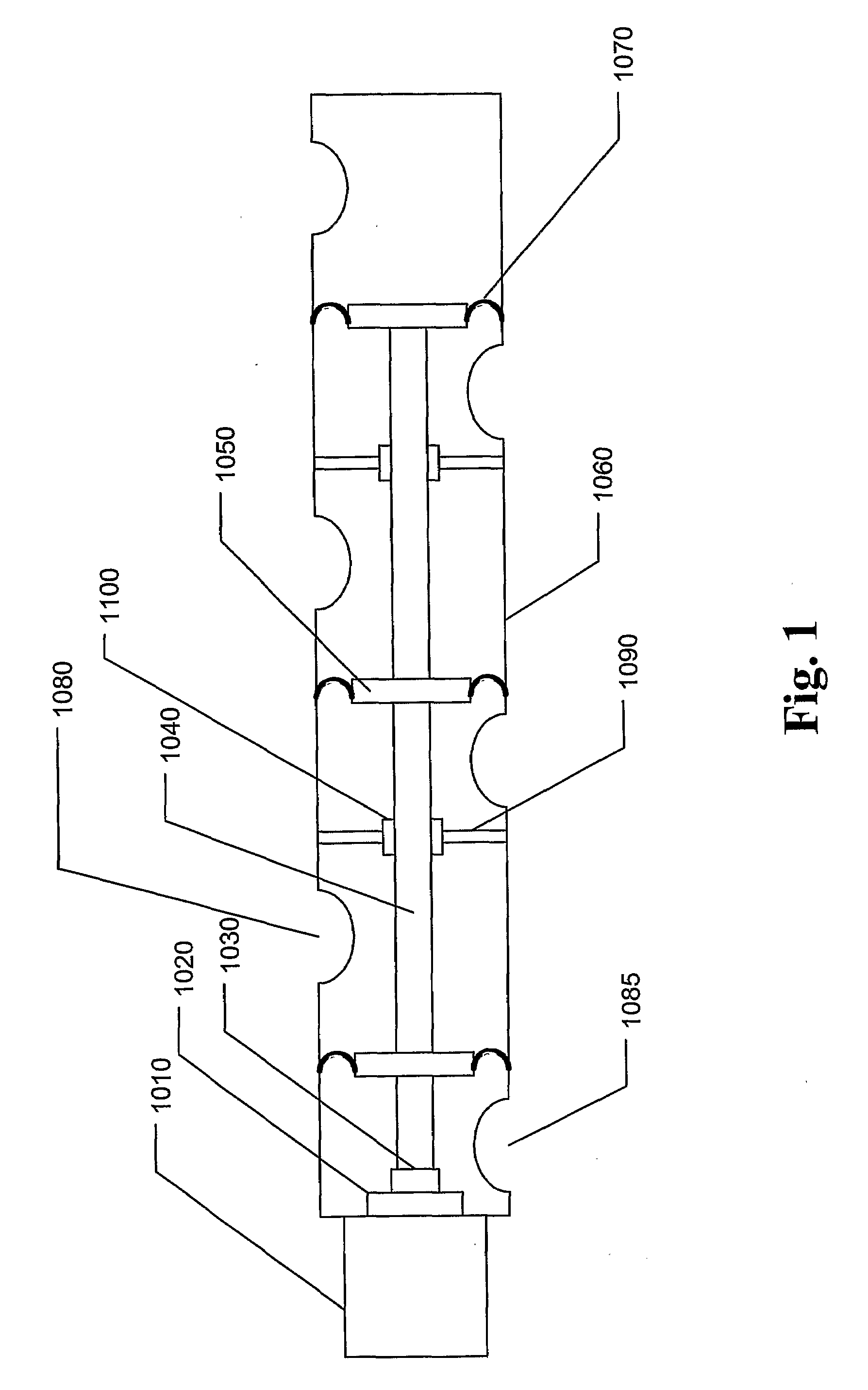
[0062]FIG. 1 shows one implementation of the invention in which an electromagnetic motor comprises a magnet 1010 and a voice coil 1020 to which is mounted a mechanical coupling 1030 that is coupled to a drive rod 1040. The drive rod is attached to the diaphragms 1050, each of which are in turn attached to the housing 1060 by a respective suspension 1070. When an audio signal is applied to the voice coil, the sound waves from one side of the diaphragms are allowed to radiate to the listening environment through the openings 1080. The sound waves from the other side of the diaphragms are allowed to radiate from another set of openings 1085. Unwanted air leakage is prevented or reduced substantially by the baffles 1090 and the seals 1100. If desired, one or more bushings may be used in the motor to prevent undesirable voice coil motion. Alternatively, the drive rod 1040 can pass through some or all of the diaphragms 1050 without using seals. The size of the space between...


PUM


Abstract

An acoustic transducer comprises one or more electromagnetic motors that drive one or more sets of multiple diaphragms to provide acoustically efficient loudspeaker systems having dimensions that allow use in applications that would be difficult or impossible with traditional transducers. The diaphragms may be driven directly, inertially or fluidically. If diaphragms are driven by rods that pass through holes in the diaphragms, noise may be generated by air that leaks through the pass-through holes. This noise may be reduced or eliminated by measures that reduce or eliminate the air leakage.

Description

TECHNICAL FIELD[0001]The present invention is related to the field of audio systems and acoustics, and pertains more specifically to providing an improved form factor for an acoustic transducer that converts electrical signals into acoustic radiation.BACKGROUND ART[0002]The general principles of moving coil electrodynamic loudspeakers are well understood. Central to the ability of a transducer to generate sound is the concept of volume displacement. The volume displacement of a transducer with a single diaphragm is equal to the effective surface area of the diaphragm multiplied by the excursion capability of that diaphragm. The greater the volume displacement of a transducer, the greater its potential for generating sound. The need for large volume displacement is especially pronounced at low frequencies. The traditional methods for achieving greater volume displacement in a transducer are to increase the surface area of the diaphragm, to increase the excursion capability of the dia...

Claims


Application Information

Patent Timeline
Patent Type & Authority Applications(United States)
IPC IPC(8): H04R1/00H04R1/40H04R9/06H04R23/00
CPCH04R9/063H04R23/02H04R2209/026H04R7/26H04R2499/13H04R2499/15H04R7/16H04R2400/11H04R9/06
Inventor UNRUH, ANDREW DAVIDTRUE, ROBERT J.NORCOTT JR., EDWARD T.AXELSSON, JENS-PETERJABBARI, ALIREZAPRINCE, DAVID J.KANTOR, KENNETH L.KANELLAKOPOULOS, IOANNISWEI, SHAOLIN
Owner TYMPHANY HK
Why Eureka
Try Eureka