Lubrication heating system and wind turbine incorporating same

a technology of lubrication heating system and wind turbine, which is applied in the direction of wind turbines, waterborne vessels, machines/engines, etc., can solve the problems of affecting the efficiency of the wind turbine, the damage and the inability of the circulating pump to heat up all the oil in the gearbox. , to achieve the effect of avoiding damage to the pump

Active Publication Date: 2009-07-30
GENERAL ELECTRIC CO
View PDF7 Cites 70 Cited by
  • Summary
  • Abstract
  • Description
  • Claims
  • Application Information

AI Technical Summary

Benefits of technology

[0006]In one aspect of the present invention a wind turbine is provided comprising a gearbox containing a lubrication medium, a pump for circulating the lubrication medium, and a gearbox lubrication suction pipe for transporting the lubrication medium from the gearbox to the pump. A heater is in thermal connection to, at least a portion of. the gearbox lubrication suction pipe. This heater is used to heat the lubrication medium contained within the gearbox lubrication suction pipe to a temperature where damage to th

Problems solved by technology

), the lubrication oil used in the gearbox can become very viscous or thick.
This cold and viscous oil resists flow and the circulating pump can be damaged if run when the oil is very cold.
This oil sump heater takes a long time to heat up all the oil in the gearbox sump and requires a la

Method used


Image

  • Lubrication heating system and wind turbine incorporating same
  • Lubrication heating system and wind turbine incorporating same
  • Lubrication heating system and wind turbine incorporating same

Examples


Embodiment Construction

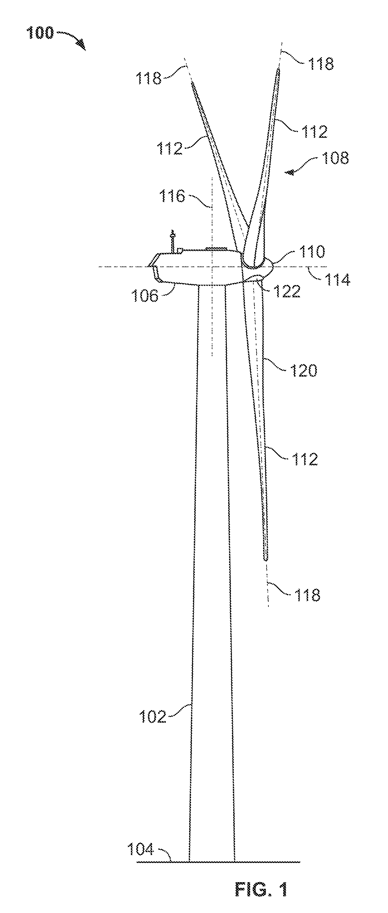
[0015]FIG. 1 is a schematic illustration of an exemplary wind turbine 100. In the exemplary embodiment, wind turbine 100 is a horizontal axis wind turbine. Alternatively, wind turbine 100 may be a vertical axis wind turbine. Wind turbine 100 has a tower 102 extending from a supporting surface 104. a nacelle 106 mounted on tower 102, and a rotor 108 coupled to nacelle 106. Rotor 108 has a rotatable hub 110 and a plurality of rotor blades 112 coupled to hub 110. In the exemplary embodiment, rotor 108 has three rotor blades 112. In an alternative embodiment, rotor 108 may have more or less than three rotor blades 112. In the exemplary embodiment, tower 102 is fabricated from tubular steel and has a cavity (not shown in FIG. 1) extending between supporting surface 104 and nacelle 106. In an alternate embodiment, tower 102 is a lattice tower. The height of tower 102 is selected based upon factors and conditions known in the art.

[0016]Blades 112 are positioned about rotor hub 110 to facil...


PUM


Abstract

A wind turbine is provided having a gearbox containing a lubrication medium, a pump for circulating the lubrication medium. and a gearbox lubrication suction pipe for transporting the lubrication medium from the gearbox to the pump. A heater is in thermal connection to, at least a portion of, the gearbox lubrication suction pipe. This heater is used to heat the lubrication medium contained within the gearbox lubrication suction pipe to a temperature where damage to the pump is avoided.

Description

BACKGROUND OF THE INVENTION[0001]This invention relates generally to rotary machines and more particularly, to a lubrication heating system for operating wind turbines in cold weather environments.[0002]Generally, a wind turbine includes a rotor having multiple blades. The blades are attached to a rotatable hub, and the blades and hub are often called the rotor. The rotor transforms mechanical wind energy into a mechanical rotational torque that drives one or more generators. The generators are generally, but not always, rotationally coupled to the rotor through a gearbox. The gearbox steps up the inherently low rotational speed of the turbine rotor for the generator to efficiently convert the rotational mechanical energy to electrical energy, which is fed into a utility grid. Gearless direct drive wind turbine generators also exist. The rotor, generator, gearbox and other components are typically mounted within a housing, or nacelle, that is positioned on top of a base that may be ...

Claims


Application Information

Patent Timeline
IPC IPC(8): F01M5/00F03D11/00F01D25/20F16H57/04
CPCF03D11/0008F05B2260/20F05B2260/98Y02E10/722F16N39/02F16N2210/12F16N2250/08F16H57/0413F03D80/70F03D80/60Y02E10/72
Inventor BAGEPALLI, BHARAT S.HIDDING, EDWINKLUMPER, STEPHANBAKER, ERIC A.GRUNWALDT, HOLGERBURKETT, MICHAEL J.
Owner GENERAL ELECTRIC CO
Why Eureka
Try Eureka