
System and method for verifying operation of a target system

a target system and system technology, applied in the field of system for verifying the operation of a target system, can solve the problems of inefficiency of observation for general purpose use, inability to verify the amount of information of the system's operation in itself is enormous, so as to reduce the difficulty of observing the operation of the target system, the effect of affecting the operation performance of the target system to be inspected

Inactive Publication Date: 2009-07-30
IBM CORP
View PDF5 Cites 25 Cited by
  • Summary
  • Abstract
  • Description
  • Claims
  • Application Information

AI Technical Summary

Benefits of technology

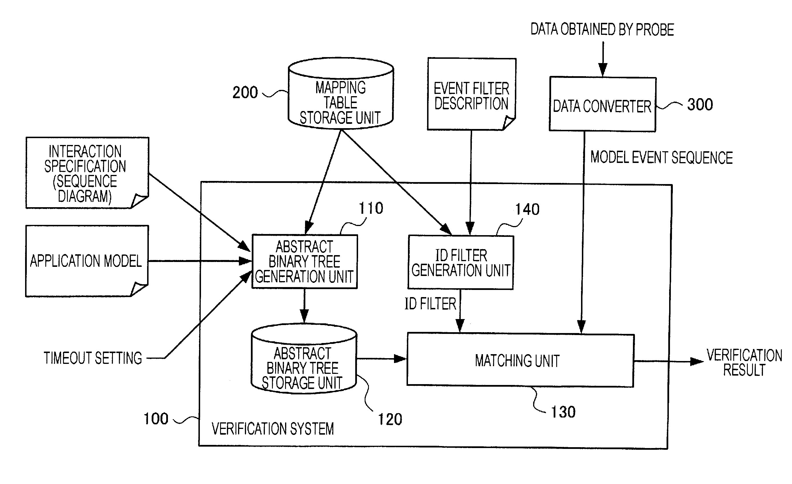
[0010]The present invention is made in view of the aforementioned problems. It is therefore an object of the present invention to provide a system, a method for observing and verifying the operation of a target system to be inspected while determining a variety of inspection conditions, and computer readable article of manufacture to implement the method of the present invention. It is another object of the present invention to reduce intrusion on operation performance of a target system to be inspected occurring in verification of the operation of the target system.
[0014]According to the present invention described above, the operation of a target system to be inspected can be observed and verified while various inspection conditions are determined. In addition, according to the present invention, intrusion on operation performance of a target system to be inspected occurring in verification of the operation of the target system can be reduced.

Problems solved by technology

Although the amount of information of the system's operation in itself is enormous, the amount of information actually recorded can fall within a practical range by recording only information sufficient for reproduction of the operation.
Accordingly, observation for general purpose use is inefficient and it is difficult to reduce intrusion.
However, the recording is aimed at determining the cause of a system crash so it does not support many other events required for debugging a system.

Method used


Image

  • System and method for verifying operation of a target system
  • System and method for verifying operation of a target system
  • System and method for verifying operation of a target system

Examples


Embodiment Construction

[0025]The embodiments of the present invention will be further described below with reference to the accompanying drawings.

[0026]In the system of the present invention, it is determined whether an application meets a functional specification of a target system to be inspected; the target system having been developed by model driven architecture. The functional specification of the target system to be inspected is described as an application model in, for example, the unified modeling language (UML). The target system executes code written in C or C++ automatically generated by the application model.

[0027]The application model of the target system is formed from a plurality of state machines (objects). The state machines are small units of elements that constitute the target system and that serve a predetermined function (not limited to hardware). Any unit of an element can be a state machine so it can be determined according to the details of inspection. Each of the state machines i...


PUM


Abstract

A system and method for verifying operation of a target system to be inspected. The system includes an abstract binary tree generation unit and a matching unit. The abstract binary tree generation unit obtains information about a functional specification of the target system and generates one or more binary trees that associate one or more states that can occur in the target system with respective nodes and that associate state transitions of objects constituting the target system and interactions between the objects with connection relationships between the nodes. The matching unit receives an event sequence in an application model of the target system obtained in response to the operation of the target system and matches the event sequence against the binary trees generated by the abstract binary tree generation unit. The method includes steps for accomplishing the functionality of the system.

Description

CROSS-REFERENCE TO RELATED APPLICATIONS[0001]This application claims priority under 35 U.S.C. §119 from Japanese Patent Application No. 2008-16771 filed Jan. 28, 2008, the entire contents of which are incorporated herein by reference.BACKGROUND OF THE INVENTION[0002]1. Field of the Invention[0003]The present invention relates to a system for verifying the operation of a target system, and more specifically, it relates to a system and method for observing and verifying the operation of a target system to be inspected while determining a variety of inspection conditions, and computer readable article of manufacture to implement the method of the present invention.[0004]2. Description of the Related Art[0005]Inspecting the operation of a real-time system, which requires processing in real time, or an embedded system, embedded in various types of devices, requires observation of the behavior of the system by actually executing software using an evaluation board or hardware of an actual ...

Claims


Application Information

Patent Timeline
IPC IPC(8): G06F11/28G06N5/02G06F17/30G06F17/00G06F7/06G06F15/16G06F11/00
CPCG06F11/3612
Inventor NAKAMURA, HIROAKIONO, KOHICHI
Owner IBM CORP
Learn More