

Hydraulic gravity harvester
- Summary
- Abstract
- Description
- Claims
- Application Information
AI Technical Summary
Benefits of technology
Problems solved by technology
Method used
Image


Examples
Embodiment Construction
[0035]Detailed descriptions of the preferred embodiment are provided herein. It is to be understood, however, that the present invention may be embodied in various forms, compounded or stacked in unison. Structural framework and fastening such as nuts and bolts are purposely omitted to provide a better general concept of the invention. It is to be understood that lubrication and / or bearings are to be used in high friction areas. Therefore, specific details disclosed herein are not to be interpreted as limiting, but rather as a basis for the claims and as a representative basis for teaching one skilled in the art to employ the present invention in virtually any appropriately detailed system, structure or manner.
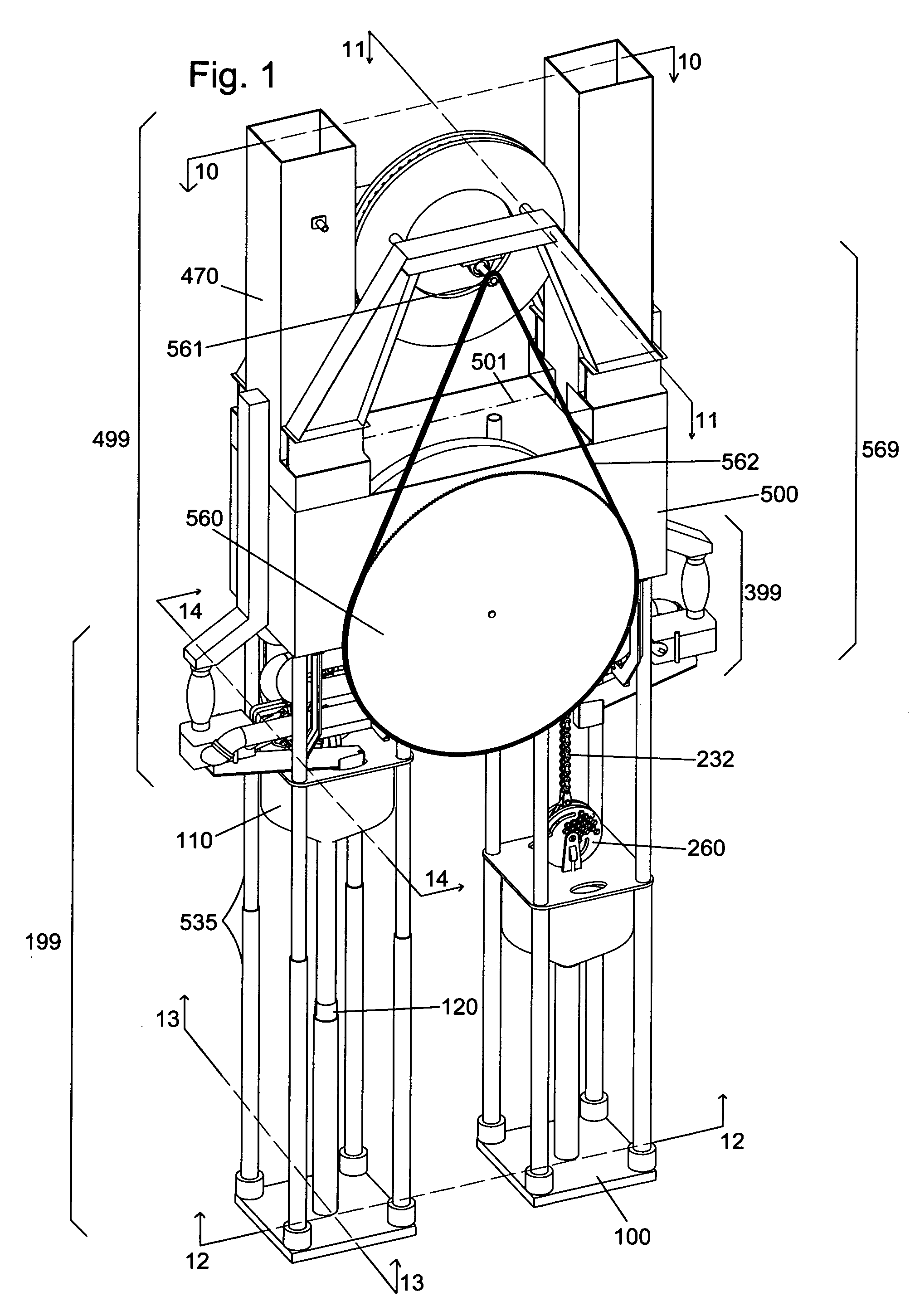
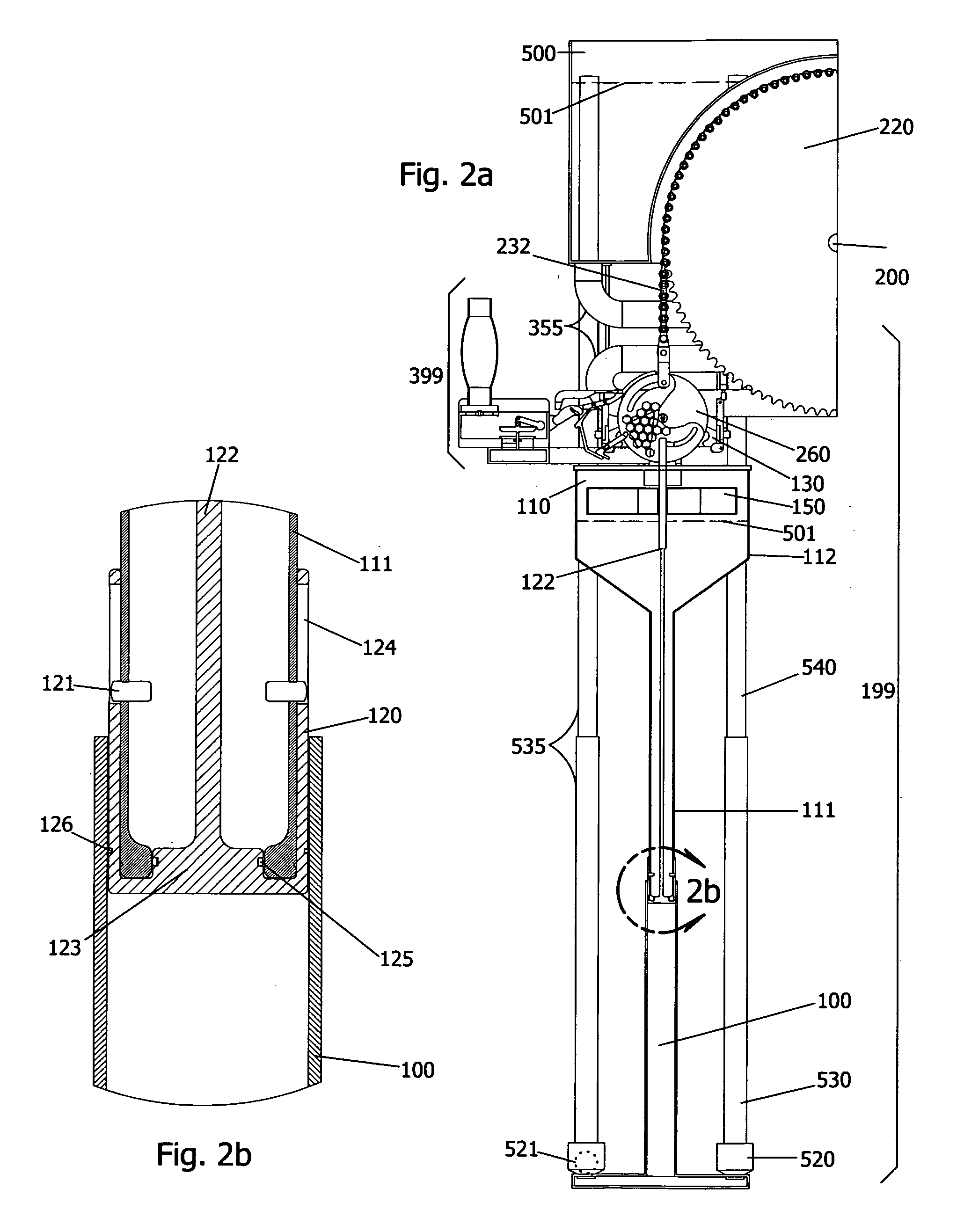
[0036]Referring to FIG. 1 there is shown a perspective view of a machine for Harvesting Energy from Gravity comprising a plural of slip bucket assemblies 199 each slip bucket assembly is generally comprised of a slip bucket sleeve 100 which houses a slip bucket piston 110 whic...
PUM
 Abstract
Description
Claims
Application Information