Jaw pipe wrench with resilient member

a resilient member and wrench technology, applied in the field of wrenches, can solve the problems of increasing the inconvenience of use, increasing the manufacturing cost and and wrenches still lack convenience in use, so as to reduce the complexity of the concatenation of elements and the manufacturing time and cost, increase the convenience of use, and increase the competitive effect of products

Inactive Publication Date: 2009-08-06
KUO SHAO FAN
View PDF18 Cites 12 Cited by
  • Summary
  • Abstract
  • Description
  • Claims
  • Application Information

AI Technical Summary

Benefits of technology

[0007]With regard to the above problems, the object of the present invention is to provide a jaw pipe wrench with resilient member which facilitates to increase the convenience of using, and reduce a complicate concatenation of elements and the manufacturing time and cost, thus increasing the competition of products.

Problems solved by technology

In this manner, users need to spend more time loosening the screw and adjusting the space of two jaws, thus increasing the inconvenience of using.
In view of the above problem, another conventional wrench relies on a toothlike element between the two jaws as disclosed in U.S. Pat. No. 6,938,525, namely, users simply press the brake lever for temporarily moving the toothlike elements away from the lower jaw, thereby urging the jaw upward and downward; however, the lower jaw and the brake lever are separately arranged, and a spring is captured by the brake lever for ensuring a resilience, which may result of the increasing of the manufacturing cost and the complicate concatenation of elements.
Furthermore, the wrench needs to be used by pressing the brake lever for adjusting the space between the jaws, the position of the brake lever thus needs consideration; that is, if the brake lever is just arranged in an improper place, it would not be facilely touched by users, thus the wrench still lacks of convenience in use.
Additionally, the upper and the lower jaws are also susceptible to wrench body with various shapes, for instance formed of square or circular configurations, and the jaws may not be in optimum fit therewith.
In this manner, the wrench can not steadily clamp objects and hence wasting time in operation.

Method used


Image

  • Jaw pipe wrench with resilient member
  • Jaw pipe wrench with resilient member
  • Jaw pipe wrench with resilient member

Examples


Embodiment Construction

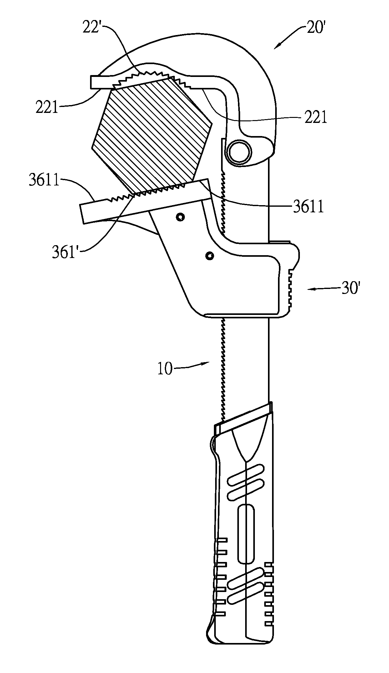
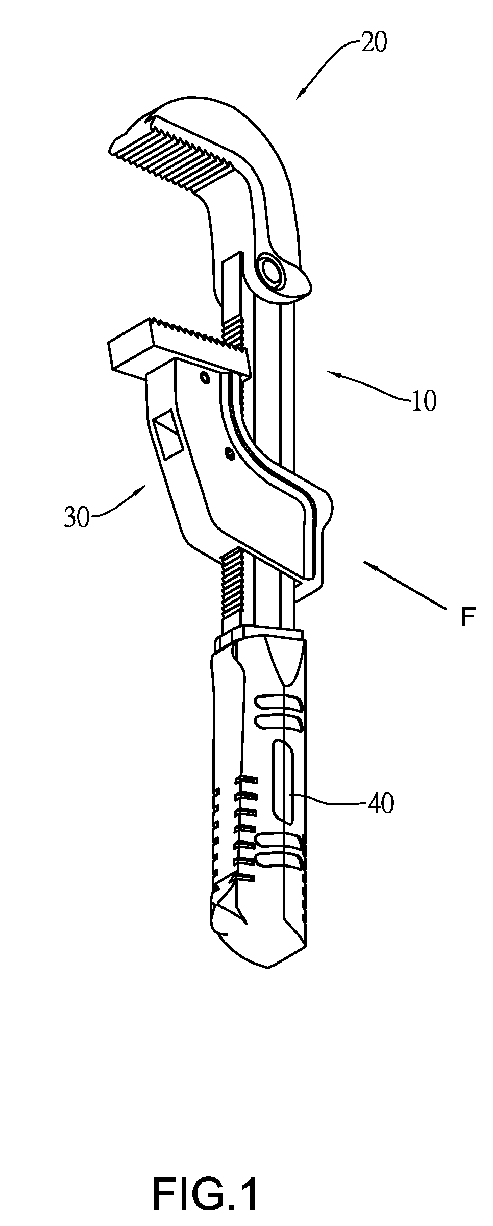
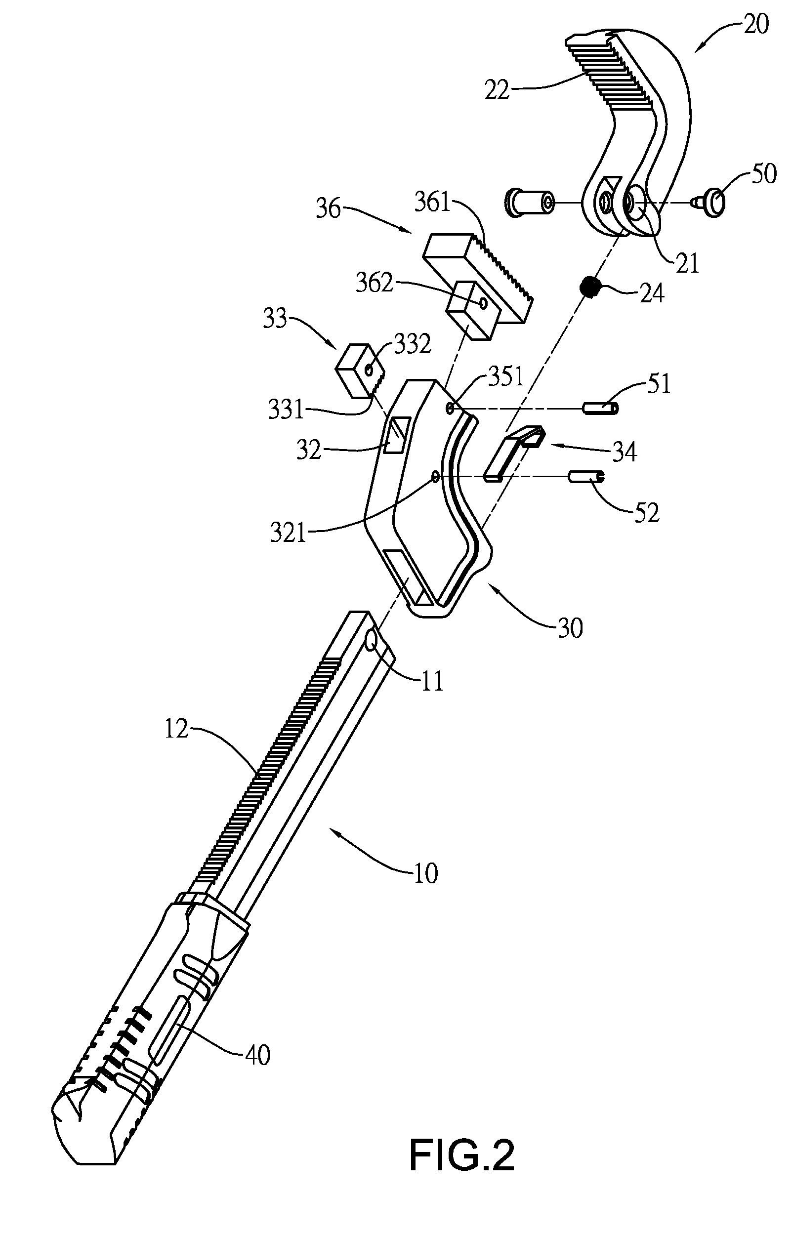
[0021]Referring to FIG. 1 and 2, a first preferred embodiment of the present invention comprises a wrench body 10, a pivotal jaw 20 pivoted to a top end of the wrench body 10, an actuating jaw 30 disposed on the wrench body 10, and a handle 40 engaged to a distal end of the wrench body 10, opposite to the pivotal jaw 20; wherein, the wrench body 10 includes a first bore 11 disposed at the top end thereof and a first serrated section 12 disposed at one side thereof; further, the pivotal jaw 20, which can be formed in an arcuate shape, comprises a second bore 21 disposed at a distal end thereof and a third serrated section 22 disposed opposite to the second bore 21; wherein the second bore 21 is in contact with the first bore 11 so as to firmly fasten the pivotal jaw 20 to the wrench body 10 by screwing a first pivot pin 50 through the two bores 21-11. The first pivot pin 50 here is adopted in a cooperation of male and female screws.

[0022]Still further, referring to FIG. 3, the actuat...


PUM


Abstract

The present invention pertains to a jaw pipe wrench with resilient member comprising a wrench body penetrating through an actuating jaw, where a resilient member mounted and provides with one flat surface leans against said wrench body, so as to drive a serrated section of the wrench body firmly contacting with a serrated section of actuating jaw. While in manipulation, users initially propel the actuating jaw and synchronically compress the resilient member, the serrated section of the wrench body thus moves away from the serrated section of the actuating jaw, whereby users can freely raise or descend the actuating jaw in time of clamping, thus increasing the convenience of using.

Description

BACKGROUND OF THE INVENTION[0001]1. Field of the Invention[0002]The present invention relates to a wrench tool, in particularly a jaw pipe wrench with resilient member.[0003]2. Description of the Related Art[0004]Generally, a conventional wrench often provides with a fastener, e.g. a screw, for screwing an upper jaw and a lower jaw, and users used to rotate the screw for adjusting the space between the two jaws. In practical, users need to have both hands grip the handle and simultaneously free the screw, further, the screw used to have small pitch for ensuring the gripping capability of the wrench. In this manner, users need to spend more time loosening the screw and adjusting the space of two jaws, thus increasing the inconvenience of using.[0005]In view of the above problem, another conventional wrench relies on a toothlike element between the two jaws as disclosed in U.S. Pat. No. 6,938,525, namely, users simply press the brake lever for temporarily moving the toothlike elements...

Claims


Application Information

Patent Timeline
Patent Type & Authority Applications(United States)
IPC IPC(8): B25B13/12
CPCB25B13/5058
Inventor KUO, SHAO-FAN
Owner KUO SHAO FAN
Why Eureka
Try Eureka