
Sorrels engine

a technology of torque engine and torque shaft, which is applied in the direction of positive displacement engines, machines/engines, mechanical equipment, etc., can solve the problems of not being practicable, too complex or unsuitable for proper cooling or lubrication, and producing marketable designs, etc., to achieve fuel efficiency, simplify manufacturing, and reduce the effect of stokes

Inactive Publication Date: 2009-08-06
SORRELS JOE MARK
View PDF11 Cites 2 Cited by
  • Summary
  • Abstract
  • Description
  • Claims
  • Application Information

AI Technical Summary

Benefits of technology

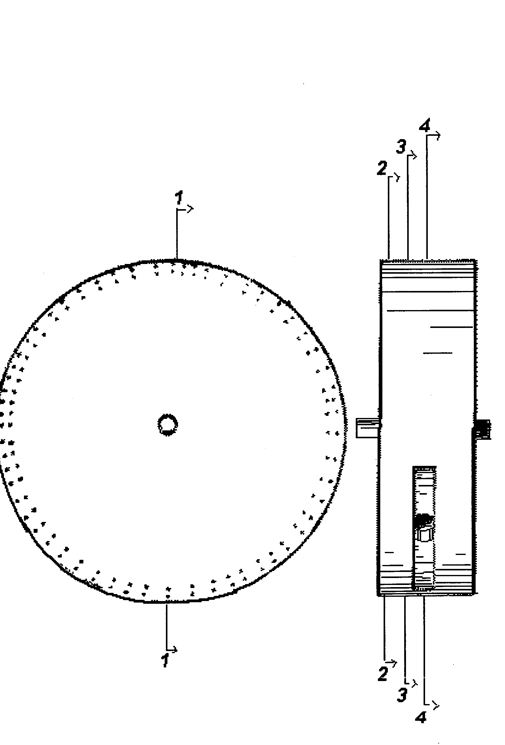
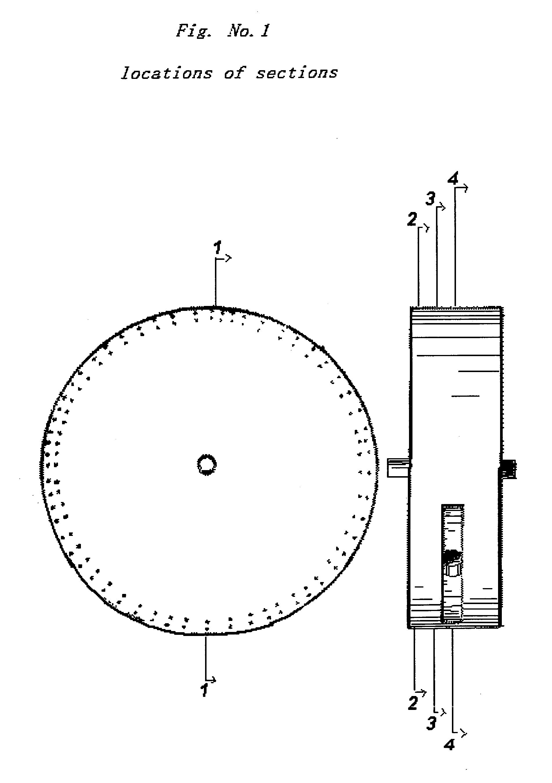
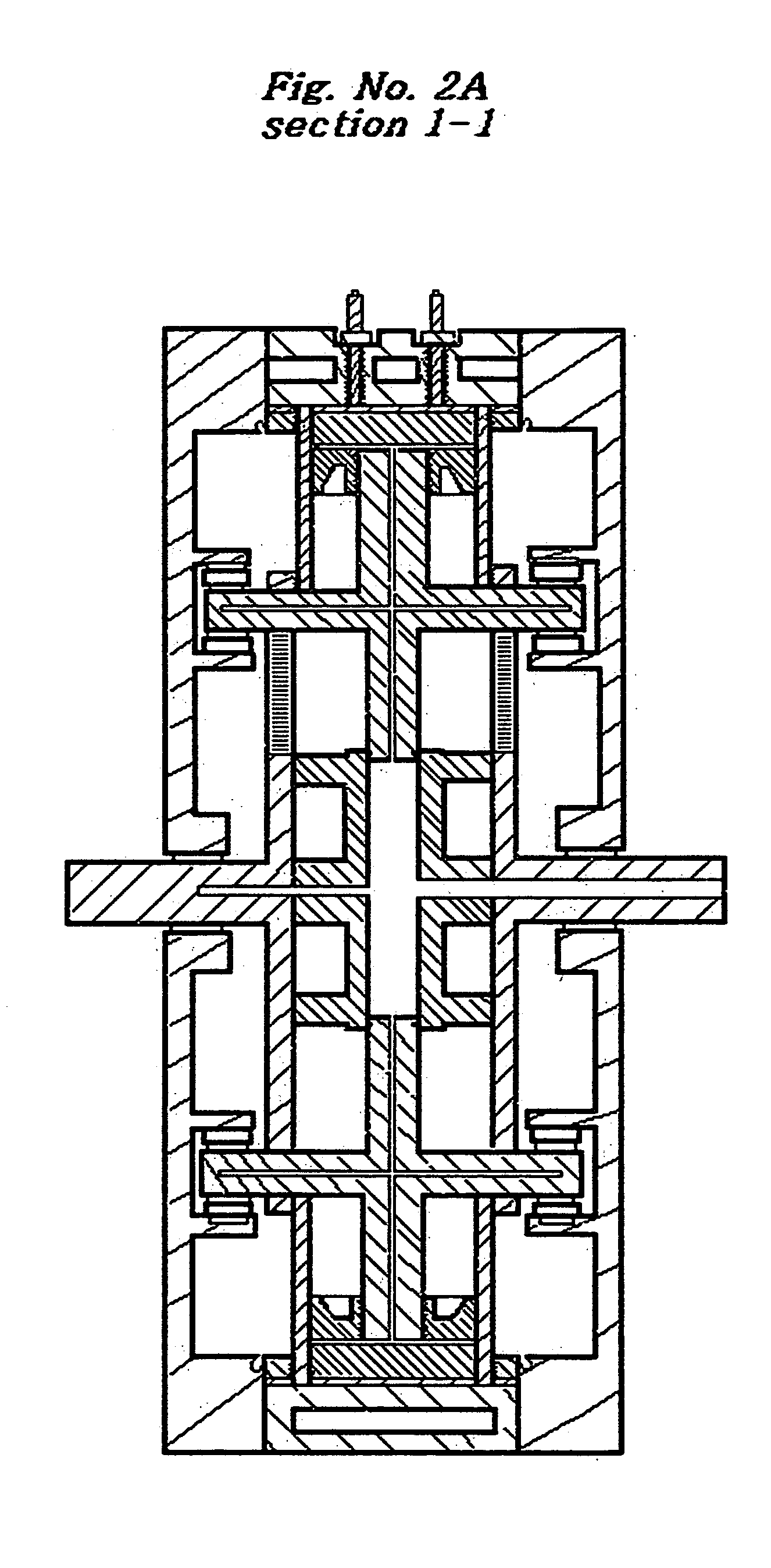
[0010]In this engine the resultant of the power stroke and resistance to the same by channels cast in the engine housings forces rotation of an upper restraining ring, pistons with rings, cylinders, channel rollers, slotted restraining plates with power shafts, connecting rods with side shafts, restraining hub and threaded spacer bars. Cylinders rotate past exhaust and intake ports in the cylinder head while channel rollers in the channels force the cycles. Engine provides a minimum of one power stroke for every cylinder every revolution with unrestricted exhaust and intake strokes. A large percentage of the mass of the engine is rotating. The advantage of this engine is no flywheel is required, complete unrestricted exhaust and intake cycles, a minimum of one power stroke every cylinder every revolution, variability in the duration of stokes, fuel efficiency, and simplified manufacturing and it produces more power relative to its weight and displacement.

Problems solved by technology

Attempts at designing rotary engines with some, most or all of the following elements; reciprocating pistons, rotating cylinders, cams and ported engine housings, have failed to produce marketable designs because they would not produce the amount power required, have much concentric motion, were limited to strokes of ninety degrees in duration, were suitable only for aircraft, were too complex or could not be properly cooled or lubricated, or could not be practically manufactured.

Method used


Image

  • Sorrels engine
  • Sorrels engine
  • Sorrels engine

Examples


Embodiment Construction

[0047]Fuel systems are not addressed in this application due to the wide variance of fuels available and the need to adapt these systems to the fuels properties.

[0048]Cooling systems are not addressed in this application due to the wide variance of fuels available and need to adapt these systems to the fuels properties.

[0049]Lubrication systems are not addressed in this application due to the wide variance of fuel available and the need to adapt these systems to the fuels properties.

[0050]Ignition and electrical systems are not addressed in this application due to the wide variance of fuel available and the need to adapt these systems to the fuels properties.

[0051]Elements of the above systems, subdivision of multifunctional elements and minor changes to the elements are not limited by this description or the claims.

[0052]A rotary four-cycle internal combustion engine that is an assemblage of single and multifunctional fixed elements comprising

[0053]a cylinder head 1 (FIGS. 2B, 4 an...


PUM


Abstract

An internal combustion engine of uniquely simple elements that combines the use of an assemblage of rotating elements to restrain cylinders radically coplanar perpendicular to centerline of the power shaft and pistons and connecting rods to a rotating coplanar reciprocating alignment with the cylinders, channels to force strokes of the pistons and connecting rods, with the energy of the power stroke and the resistance of the same by the channels producing a force that rotates the assemblage inside a ported engine housing. Engine should be lighter, able to use a variety of fuels, able to use simplified ignition systems, produce more power and be more cost efficient to manufacture and operate than existing engines of the same displacement. Once engine position and fuel is decided elements of the fuel, cooling, lubrication, ignition and electrical systems can be included in the drawings.

Description

CROSS-REFERENCE TO RELATED APPLICATIONS[0001]Not ApplicableSTATEMENT REGARDING FEDERALLY SPONSORED RESEARCH OR DEVELOPMENT[0002]Not ApplicableREFERENCE TO SEQUENCE LISTING, A TABLE, OR A COMPUTER PROGRAM LISTING COMPACT DISC APPENDIX[0003]Not ApplicableBACKGROUND OF THE INVENTION[0004]1. Field of the Invention[0005]Same as typical for existing four and two cycle engines.[0006]U.S. CL . . . 123 / 44C; 123 / 44D; 123 / 45R; 123 / 54.3[0007]2. Background Art[0008]Existing four cycle engines utilize crankshafts that provide little mechanical advantage, have restricted intake and exhaust cycles, existing four cycle engines must store energy in flywheels to smooth power strokes, existing four cycle engines can provide only one power stroke per cylinder every other revolution and have strokes that are limited to each being ninety degrees of revolution. Two cycle engines are polluters.[0009]Attempts at designing rotary engines with some, most or all of the following elements; reciprocating pistons,...

Claims


Application Information

Patent Timeline
Patent Type & Authority Applications(United States)
IPC IPC(8): F01B3/00
CPCF02B57/08F01B9/06
Inventor SORRELS, JOE MARK
Owner SORRELS JOE MARK
Learn More